1.1 Project Overview
The project is located at an electric vehicle charging station in Shanghai. The existing charging station is planned to be converted into a combined solar-storage-charging demonstration site. This station currently has 22 parking spaces, each equipped with a 60kW DC charging station. Parking spaces 1-8 are covered by canopies; spaces 9-13 are open-air; and spaces 14-22 are located in the ground-floor garage on the first floor of the office building. Charging stations 1-12 are powered by 800kVA box-type transformer 1; charging stations 13-22 are powered by 630kVA box-type transformer 2.
Based on on-site analysis, solar panels can be installed on the roof of the office building. At the same time, the canopies 1-8 will be converted into a PV carport. The south side of parking spaces 9-13 will remain unchanged due to the height of the trees, making it difficult to install PV modules. The energy storage equipment will be located in the ground-floor garage on the first floor of the office building and directly connected to box-type transformer 2 via an existing cable trench. The existing charging stations will remain unchanged, creating a combined solar-storage-charging demonstration site. If the photovoltaic system's power output exceeds the charging station's consumption during operating hours, energy storage are used to store the excess power. When the photovoltaic power generation is insufficient to support the charging station's consumption, the energy storage is combined with the grid to provide power, maximizing the system's economic efficiency.
1.2 The Significance of Combining Photovoltaic and Energy Storage Charging Stations
With the continuous development of the economy, electricity demand continues to grow, and energy consumption, especially thermal power consumption, has also increased. This has caused pollution and greenhouse gas emissions, profoundly impacting our lives. Photovoltaic power generation systems, as a proactive energy-saving approach, generate and consume electricity locally, resulting in excellent environmental and economic benefits. However, photovoltaic power generation is unstable. While ideal power generation can be achieved under favorable sunlight conditions, sunlight and other environmental factors vary in real time, making photovoltaic power generation unstable. The introduction of energy storage systems can address this unstable power supply.
Electrochemical energy storage includes typical secondary battery systems such as lithium-ion batteries, flow batteries, lead-acid batteries, and sodium-sulfur batteries, as well as emerging secondary battery systems (sodium-ion batteries, lithium-sulfur batteries, and lithium-air batteries). For power systems, the fundamental technical characteristics of energy storage systems are reflected in their power levels and duration. This duration is a key differentiator from traditional, on-demand devices. The introduction of energy storage systems not only addresses the instability of photovoltaic power generation but also addresses issues such as wasted photovoltaic power generation caused by mismatches between charging station usage and photovoltaic power generation periods.
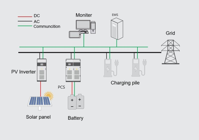
PV Storage Charging System Topology
1.3 Advantages of PV Storage and Charging
(1) Reasonable use of land resources
The photovoltaic modules are arranged on the roof of the office building and the top of the parking canopy respectively. They are all transformed on existing resources, do not occupy excess land resources, and can make more efficient use of existing land resources.
(2) Superior economic efficiency
PV power generation can be directly used to power parking charging piles. When the charging pile load is not enough to consume photovoltaic power, it can be stored through the energy storage system. When the charging load is greater than the photovoltaic power generation, it can be discharged.
According to the power supply business rule, the power grid company charges different electricity prices according to different peak and valley periods. The peak-valley price difference can reach 0.11 USD/kWh. The energy storage system can store electricity during the valley period and discharge it during the peak electricity price period, thereby obtaining economic benefits through the price difference.
(3) Reduce transformer capacity
This project plans to install a 100kW/215kWh energy storage systems (lithium ion solar battery); the energy storage can be combined to reduce the transformer capacity burden when the charging station load is large, ensuring the quality of electricity use while reducing the monthly capacity electricity fee.
2.Overall system design
2.1 Project design features High reliability: The photovoltaic, energy storage and charging system is optimized, the equipment and components are of reliable quality and can be used without power outages. PV design life is not less than 20 years, and lithium ion solar battery cycle life is not less than 6,000 times.
High economy: The photovoltaic modules generate electricity in real time under sunlight, effectively utilizing light resources and saving electricity costs. Energy storage system can smooth out the peak and fill the valley, and obtain income from the peak-valley price difference.
High system efficiency: The photovoltaic modules are made of monocrystalline silicon material, with a nominal power of not less than 540Wp under stable efficiency and an overall power generation efficiency of not less than 82%. Energy storage system uses lithium iron phosphate battery , and the charging-discharging efficiency is not less than 92%.
Safety: PV panels offer dual security features, including protection against lightning strikes, falls caused by strong winds, and electric shock. The solar battery management system features a three-level protection system that constantly monitors the battery's operating status, addressing safety concerns.
User-friendly: Both PV and energy storage systems utilize cloud-based systems, enabling multi-device access and remote control. Users can view power generation, battery status, and accumulated power generation in real time.
2.2 Photovoltaic Design
PV system, installed on the roof of the carport and the office building, is designed as a grid-connected system, with generated electricity consumed locally. The system operates by connecting solar panels in series to generate direct current (DC) power, which is then connected to the DC side of an inverter. The inverter then converts the DC power to AC, which is then connected to a low-voltage busbar for grid connection. This low-voltage busbar also connects the system to the energy storage system, charging stations, and other equipment. The system primarily consists of a photovoltaic module array, a string-type grid-connected inverter, a step-up transformer, a grid-connected distribution cabinet (box), and distribution cables.
2.2.1 Photovoltaic System Configuration
The designed installed capacity is 67.58 kW. 124 monocrystalline 545W modules are used; each string consists of 16/11 modules. Two 30 kW string-type inverters are used.
After power conversion by the inverter, the system is connected to the grid via a grid connection point connected to the low-voltage grid connection point on the secondary side of the No. 1 box-type transformer.
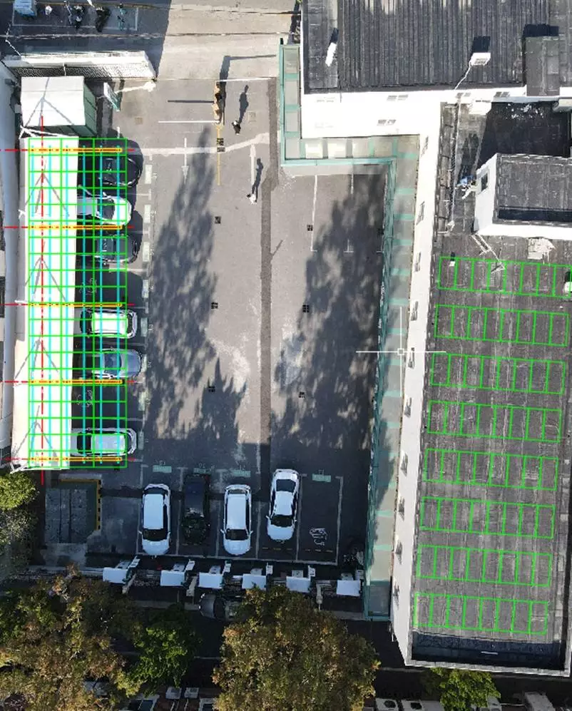
Solar Panel Layout Diagram
The inverter is placed under solar panels, and the cable is temporarily laid down from the roof of the guard room to the wall, and then connected to the transformer box 1 through the original cable trench.
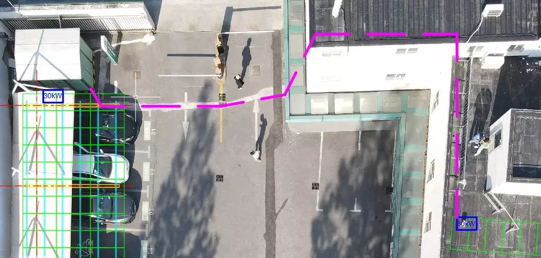
Schematic Diagram of Inverter Installation and Photovoltaic Cable Routing
2.3.2 Grid Connection Principle and Metering
The photovoltaic power generation system is designed as an online, unattended grid-connected system. There is no intermediate power switching or switching time, enabling "inductive power consumption." The system is connected to a designated grid connection point via a photovoltaic grid-connected distribution box.
The photovoltaic system's grid connection principle relies on real-time acquisition of grid electrical signals (voltage, frequency, and phase) to maintain uniform voltage, frequency, and phase. Its output electrical parameters fully meet the State Grid's requirements for distributed power generation grid connection and meet the State Grid's power quality requirements, such as the allowable deviation of the power system's supply voltage.
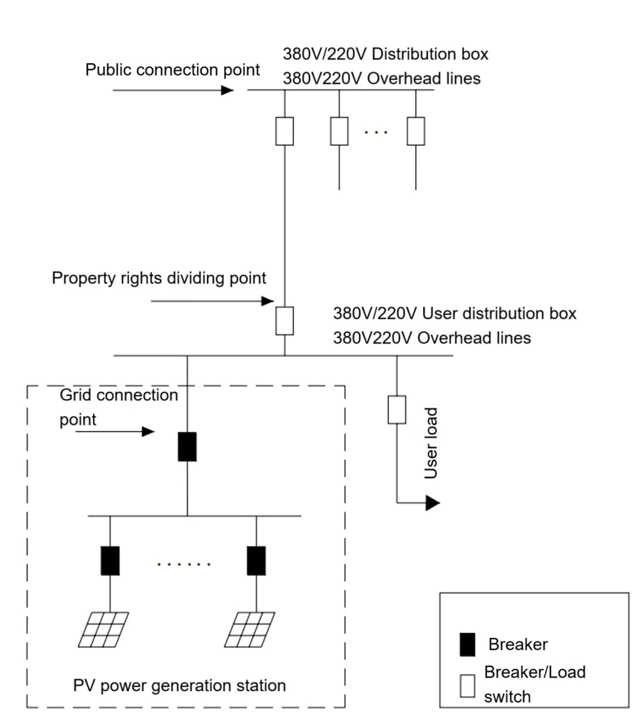
PV Power Generation System Grid Connection Diagram
Photovoltaic power is preferentially distributed to charging stations. If the photovoltaic power is insufficient to support the charging station load, the energy storage system will be used for power if available, otherwise power will be drawn directly from the grid. If the photovoltaic power generation exceeds the load consumption, the photovoltaic power generation will be transmitted to the energy storage system.
2.3.3 Selection of Key Equipment and Materials
2.3.3.1 Selection of Solar Panels
Based on comprehensive consideration of the industry landscape, technological maturity, operational reliability, and future technological development trends of various currently commercialized solar panels, and following market research, this project has determined that, among the currently mature, large-capacity solar panel specifications, 124 monocrystalline silicon high-efficiency solar panels with a power output of 545Wp are suitable. Their key technical parameters are shown in the table:
| Solar panel parameters | |
| Maximum Power (Pmax/W) | 545 |
| Open Circuit Voltage (Voc/V) | 49.4 |
| Short Circuit Current (Isc/A) | 13.95 |
| Voltage at Maximum Power (Vmp/V) | 41.5 |
| Current at Maximum Power (Imp/A) | 13.14 |
| Module Efficiency(%) | 21.3% |
| OperatingTemperature | -40℃ ~ +85℃ |
| Power Output Tolerance | 0 ~ 3% |
| Maximum System Voltage | 1500VDC |
| Maximum Series Fuse Rating | 30A |
| Nominal Operating Cell Temperature | 45±2℃ |
| Protection Class | Class II |
2.3.3.2 PV Inverter Selection
As the PV inverter device that converts DC power into AC power in a SOLAR power generation system, it is the brain of the system. Its selection plays a crucial role in the conversion efficiency and reliability of the power generation system. The preliminary design for this project selected two 30kW string-type grid-connected inverters.Specific parameters are shown in the table below.
| Parameters | |
| Maximum input voltage | 1100V |
| Minimum input voltage/starting voltage | 160V/200V |
| Rated input voltage | 600V |
| MPPT voltage range | 160-1000V |
| Full-load MPPT voltage range | 550V-850V |
| Maximum input current | 90A |
| MPPT | 3 |
| Output (AC) | |
| Rated output power | 30kW |
| Maximum output power | 33kW |
| Maximum output apparent power | 33kVA |
| Maximum output current | 50.2A |
| Rated grid voltage | 3L/N/PE,220/380V,230/400V |
| Grid voltage range | 312-480V |
THDI | < 3 % |
| Power factor | 0.8 leading-0.8 lagging |
| Efficiency | 98.70% |
| Protection | |
Island protection | Yes |
| Low-voltage ride-through | Yes |
| DC reverse connection protection | Yes |
| ACshort-circuit protection | Yes |
| Leakage current protection | Yes |
| DC switch | Yes |
| String detection | Yes |
| Surge protection | Yes |
| General parameters | |
| Operating temperature range | -30~+60 ℃(> 50 ℃ derating) |
| Working humidity range | 0~100% |
| Cooling method | Air-cooling |
| Maximum working altitude | 5000m (>4000m derating) |
2.3.3.3 Design and Selection of Solar Mounting System
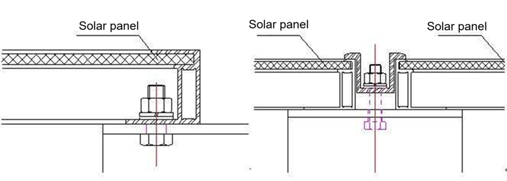
The solar panel mounting are made of hot-dip galvanized Q235 high-quality steel. The solar panel installation brackets are firm and beautiful, and the installation is quick and easy. No secondary processing of parts is required on site. Minimize on-site welding and other work.The arrangement of PV arrays needs to take into account the actual situation of the roof and be organically integrated with the local natural environment. At the same time, the design should be standardized, reserve operation and maintenance space, and take into account the landscape effect of PV distributed projects. In the design of the entire array field, the roof area should be fully utilized as much as possible. The concrete flat roof module is designed with a 15° inclination angle.
The solar mounting brackets include a set of matching stainless steel bolts, gaskets, and nuts. The special pressure blocks and other materials for the components are pre-assembled in the factory and shipped to ensure one-time availability. Except for special circumstances, there are no openings on site, and there is less welding except for lightning protection welding, less noise, and no impact on normal operation. The bracket ports have protective end caps to ensure that the ports are not damaged by bumps. Advantages are reflected in the details.
(1) The solar panel mounting brackets and their materials should meet the design requirements and meet the requirements of resistance to harsh environments, that is, wind resistance, corrosion resistance, rust resistance, etc.
(2) Solar brackets should be installed on the foundation according to the design requirements, with accurate positioning, installation tolerances that meet the design requirements, and securely fixed to the foundation.
(3) The bracket should be reliably connected to the grounding system.

2.3.3.4 Lightning protection system design
Distributed photovoltaic systems are mainly designed to protect against direct lightning strikes, induced lightning strikes, and intrusive lightning waves.
(1) Direct lightning protection
Considering the low installation height of solar panels, no lightning protection devices such as lightning rods and lightning conductors are installed in the photovoltaic array. Reliably connect the solar panel frame to the bracket and then to the grounding grid. To increase the lightning current dispersion effect, all solar brackets in the station can be reliably connected.
The inverter and local step-up transformer casing are reliably connected to the main grounding grid. To prevent corrosion, hot-dip galvanized materials are uniformly used for grounding materials throughout the station.
(2) Induced lightning protection
The layout of grounding wires and grounding electrodes for induced lightning overvoltage should comply with the requirements of DL/T620-2012 "Overvoltage Protection and Insulation Coordination of AC Electrical Installations"; the grounding resistance for lightning protection should not be greater than 30Ω. In order to prevent induced lightning, surges, etc. from causing overvoltage and damaging the grid-connected equipment in the distribution room, the lightning protection measures mainly use lightning arresters.
2.3.4 Solar power generation calculation table
| Electricity Generation Forecast Table | |||
| Power | 545 Wp | Quantity | 124 PCS |
| Peak sunshine hours | 3.46 h | System efficiency | 83% |
| Year | Attenuation ratio | Convert attenuation to effective utilization hour | Annual projected power generation |
| 1 | 2% | 1238 | 69421 |
| 2 | 1% | 1225 | 68727 |
| 3 | 0.55% | 1219 | 68349 |
| 4 | 0.55% | 1212 | 67973 |
| 5 | 0.55% | 1205 | 67599 |
| 6 | 0.55% | 1199 | 67227 |
| 7 | 0.55% | 1192 | 66858 |
| 8 | 0.55% | 1185 | 66490 |
| 9 | 0.55% | 1179 | 66124 |
| 10 | 0.55% | 1172 | 65760 |
| 11 | 0.55% | 1166 | 65399 |
| 12 | 0.55% | 1160 | 65039 |
| 13 | 0.55% | 1153 | 64681 |
| 14 | 0.55% | 1147 | 64326 |
| 15 | 0.55% | 1140 | 63972 |
| 16 | 0.55% | 1134 | 63620 |
| 17 | 0.55% | 1128 | 63270 |
| 18 | 0.55% | 1122 | 62922 |
| 19 | 0.55% | 1116 | 62576 |
| 20 | 0.55% | 1109 | 62232 |
| 21 | 0.55% | 1103 | 61890 |
| 22 | 0.55% | 1097 | 61549 |
| 23 | 0.55% | 1091 | 61211 |
| 24 | 0.55% | 1085 | 60874 |
| 25 | 0.55% | 1079 | 60539 |
| Total energy in 25 years 1618627kWh | |||
2.4 Energy Storage Design
2.4.1 Energy Storage System Configuration
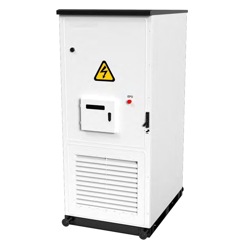
The system is designed as an integrated energy storage cabinet system, tentatively configured at 100kW/215kWh. So in this case ,we use Brovolt 100kw/215kWh solar batteries.The system is connected to the low-voltage busbar after power conversion via an energy storage converter. The energy storage system's main components include: a solar battery cabinet, a battery management system (BMS), a power conversion system (PCS), an energy management system (EMS), and auxiliary systems (including a temperature control system, fire protection system, and video surveillance system). The energy storage system design requires: Lithium iron phosphate battery packs as the energy storage medium, connected to the grid via PCS. The main functional requirements for the energy storage system design are as follows:
Battery safety management: The energy storage system is equipped with a battery management system (BMS) to manage battery charging and discharging online, provide real-time monitoring, and provide multi-level battery protection.
Energy management: BMS is connected to the PCS and back-end monitoring. Through the EMS, appropriate charge and discharge control strategies can be set according to specific regional electricity pricing standards, enabling unmanned charging and discharging of the energy storage system and reducing operating costs.
Ambient temperature design: The energy storage system is equipped with industrial air conditioning. Through the system's heat dissipation design, the temperature inside the box can be quickly adjusted and maintained stable.
Fire safety requirements: The energy storage system is equipped with an aerosol fire extinguishing system, which automatically and rapidly triggers fire alarms and extinguishes fires to protect system safety.
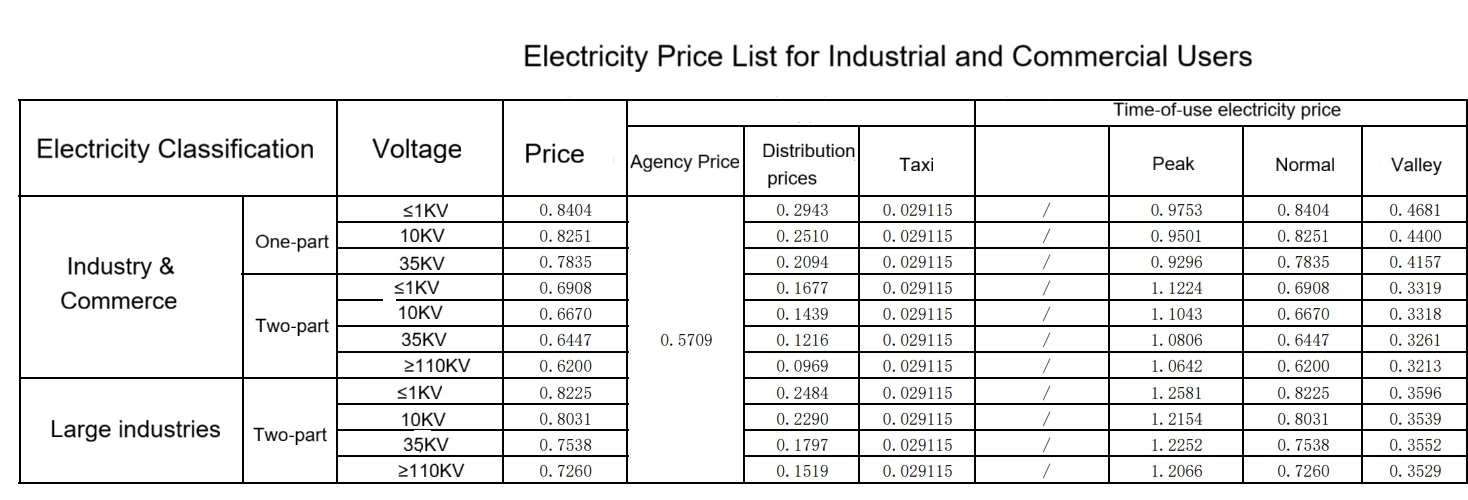
2.4.2 Electricity Prices
According to the latest State Grid-issued time-of-use electricity prices for October 2022, a two-part time-of-use electricity price system will be used: non-summer peak hours (8:00-11:00, 18:00-21:00), normal hours (6:00-8:00, 11:00-18:00, 21:00-22:00), and off-peak hours (22:00-6:00 the following day).
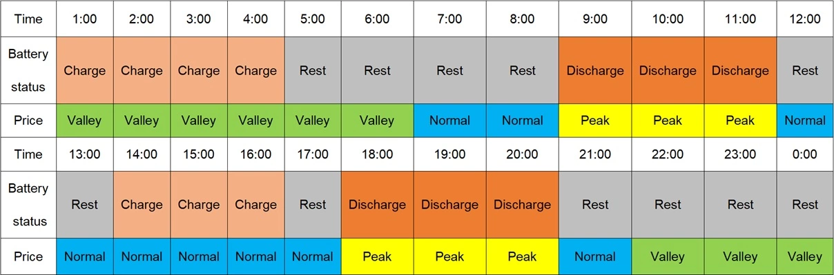
2.4.3 Charging and Discharging Mode
Based on the peak and valley periods of electricity prices in the Xuhui District, the energy storage system adopts a two-charge, two-discharge mode. The energy storage system is charged during the nighttime valley period (12:00-8:00) and discharged during the first daytime peak period (9:00-11:00). Charging occurs between 3:00 PM and 6:00 PM (if there is excess photovoltaic power generation, charging is performed using the photovoltaic system; if there is insufficient photovoltaic power generation, charging is performed using the grid), and discharging occurs during the evening peak period (6:00 PM-21:00).
2.4.4 Energy Storage System
| Battery cell | |
| Cell type | LiFePO4 |
| Voltage | 3.2V |
| Nominal capacity | 280Ah |
| Nominal charge current | 140A |
| Maxmium charge current | 280A |
| Nominal discharge current | 140A |
| Maxmium discharge current | 280A |
| Voltage range | 2.5-3.65V |
| Cycle life | >6000times,0.5C@25℃,DOD80% |
| Storage temperature | -20℃~60℃ |
| Operating temperature | -30℃~55℃ |
| Humidity | 5%-90% |
| Battery module | |
| Configuration | 1P16S |
| Nominal energy | 14.336kWh |
| Nominal voltage | 51.2V |
| Charge-discharge rate | 0.5C |
| PCS parameters | |
| Nominal power | 100kW |
| Maximum output power | 110kVA |
| Nominal frequency | 50Hz/60Hz |
| Nominal current | 144A |
| Power factor | 0.8 leading-0.8 lagging |
| Nominal voltage | 400V |
| THDi | <3% |
| Cooling method | Air-cooling |
| Communciation port | RS485,CAN ,LAN |
2.4.5 EMS for Energy Storage System
EMS performs real-time monitoring and data collection for the entire energy storage system, and manages the energy storage process. It also monitors the power grid load in real time, achieving unified management of the entire system.
1 .Real-time Monitoring of System Operation Status
The system can collect real-time and scheduled data for all monitored operating parameters and status, process important historical data, and store it in a database. This includes:
Common information such as the total voltage, current, average temperature, SOC, SOH, charging/discharging current and power limits of each battery pack in BMS , the maximum/minimum cell voltage and temperature, fault and alarm information, historical charging/discharging capacity, and historical charging/discharging energy.
Relevant parameters of the PCS, including: DC side voltage/current/power, AC side active power, reactive power, voltage, current, power factor, frequency, temperature, cabinet temperature, operating status, alarm and fault information, daily charging/discharging capacity, and cumulative charging/discharging capacity.
Information on load voltage, current, active power, reactive power, frequency, etc.
2 System Operation Data Display
The system allows users to customize the data displayed on the interface according to their needs, enabling real-time and historical data viewing and report generation.
3 Economic Operation Strategy
Compared to the economic operation analysis of conventional power systems, which mainly calculates the transformer loss curve under various operating modes, the economic operation analysis of microgrid systems replaces the transformer with a PCS and inverter for calculation. It analyzes the current energy storage capacity and load ratio to determine the optimal operating strategy and execute optimization commands.
4 Fault Alarm
The system provides event recording and query functions for different levels of events, using color coding to distinguish and manage event types and severity.
5 Reports, Real-time Curves, and Energy Flow Display
The system provides real-time curve recording, analysis, and query functions. Users can freely select the data to be recorded and analyzed. Real-time data, historical data, and statistical values are displayed as curves and bar charts. Statistical data intervals are 5 minutes, 15 minutes, 1 hour, and 1 day.
6. Data Analysis
Common data analysis tools include energy flow diagrams, cost accounting, energy saving analysis, production energy efficiency analysis, energy consumption forecasting, and benchmarking analysis.
7. System Performance Analysis
Economic performance analysis primarily relies on energy management system modeling to assess the overall system efficiency, considering factors such as PCS output and the state of health (SOH) of the energy storage system.
2.4.5 Fire Protection System
Fire alarm and control system + Aerosol-based automatic fire suppression system
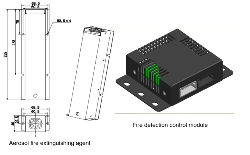
The fire control module features high sensitivity and reliability, enabling rapid response to conditions within the integrated cabinet and controlled aerosol extinguishing. The aerosol spray floods every corner of the fire, rapidly extinguishing it.The system is maintenance-free, with the detection module operating for over eight years and the fire extinguishing agent lasting ten years. It is environmentally friendly, leaving no pollution after extinguishing the fire, ensuring a green and environmentally friendly environment.
2.4.6 Air Conditioning System
Air conditioning system uses a condensing fan and evaporating fan with a low-DC brushless fan, boasting a service life of up to 20 years. The entire system meets IP55 protection, with an internal electrical protection rating of up to IP67 and a corrosion resistance rating of C5. It also offers dual protection against condensation. During spring and winter, when the ambient temperature is below zero, the integrated cabinet must activate the heating mode to adjust the internal temperature to 16°C before starting. The air conditioning is then placed in standby mode. During summer and autumn, when the ambient temperature is higher, the air conditioning and fan control strategies lower the internal temperature of the system, maintaining a relatively stable operating temperature for the battery cells.
| Item | Year | 1 | 2 | 3 | 4 | 5 |
| Construction scale | ||||||
| 1 | PV capacity kWp | 67.58 | ||||
| 2 | ESS capacity kWh | 215 | ||||
| 3 | Total charge pile power | 1320 | ||||
| Electricity tariff rate | ||||||
| 1 | Peak price | 1.1224 | 1.1224 | 1.1224 | 1.1224 | 1.1224 |
| 2 | Normal price | 0.6908 | 0.6908 | 0.6908 | 0.6908 | 0.6908 |
| 3 | Valley price | 0.3319 | 0.3319 | 0.3319 | 0.3319 | 0.3319 |
| 4 | Peak-valley price difference | 0.7905 | 0.7905 | 0.7905 | 0.7905 | 0.7905 |
| 5 | Peak-normal price difference | 0.4316 | 0.4316 | 0.4316 | 0.4316 | 0.4316 |
| Photovoltaic earnings | ||||||
| 1 | Attenuation ratio | 2% | 1% | 0.55% | 0.55% | 0.55% |
| 2 | Peak sunshine h (h) | 3.46 | 3.46 | 3.46 | 3.46 | 3.46 |
| 3 | Effective h (h) | 1238 | 1225 | 1219 | 1212 | 1205 |
| 4 | System efficiency (%) | 83% | 83% | 83% | 83% | 83% |
| 5 | Annual power generation (kWh) | 69421 | 68727 | 68349 | 67973 | 67599 |
| 6 | Equivalent electricity price (RMB) | 0.82028 | 0.82028 | 0.82028 | 0.82028 | 0.82028 |
| 7 | Annual power generation revenue (RMB) | 56944.7 | 56375.3 | 56065.2 | 55756.8 | 55450.2 |
| ESS earnings | ||||||
| 1 | Battery decay (%) | 0 | 2.5 | 2.5 | 1.5 | 1.5 |
| 2 | Battery capacity (%) | 100 | 97.5 | 95 | 93.5 | 92 |
| 3 | System capacity (kWh) | 215 | 210 | 199 | 186 | 171 |
| 4 | Depth of discharge (%) | 90 | 90 | 90 | 90 | 90 |
| 5 | Energy storage efficiency (AC side) | 92% | 92% | 92% | 92% | 92% |
| 6 | Actual capacity used (kWh) | 178 | 173.5 | 164.8 | 154 | 141.6 |
| 7 | Reduced transformer capacity (KVA) | 40 | 40 | 40 | 40 | 40 |
| 8 | Monthly capacity electricity fee savings (RMB) | 907.2 | 907.2 | 907.2 | 907.2 | 907.2 |
| 9 | Monthly operating days | 30 | 30 | 30 | 30 | 30 |
| 10 | Monthly transferred electricity (kWh) | 4968 | 4843 | 4601 | 4302 | 3958 |
| 11 | Monthly peak-valley arbitrage (RMB) | 3927.2 | 3829 | 3637.6 | 3401.1 | 3129 |
| 12 | Monthly peak-offset arbitrage (RMB) | 1715.4 | 1672.5 | 1588.8 | 1485.6 | 1366.7 |
| 13 | Annual peak-valley arbitrage (RMB) | 47126.4 | 45948.3 | 43650.9 | 40813.6 | 37548.5 |
| 14 | Annual peak-normal arbitrage (RMB) | 20584.2 | 20069.6 | 19066.1 | 17826.8 | 16400.7 |
| 15 | Annual peak-normal arbitrage (RMB) | 78597.1 | 76904.3 | 73603.4 | 69526.8 | 64835.6 |
| Total Annual revenue (RMB) | 135541.8 | 133279.6 | 129668.6 | 125283.6 | 120285.7 | |