This design document presents a comprehensive plan for a residential rooftop photovoltaic power generation system. Based on national design standards and specifications, the system is carefully tailored to local solar radiation resources and the building’s roof conditions. It adopts high-efficiency monocrystalline silicon modules and a string inverter, ensuring stable power output, safety, and reliability.
The project aims to maximize the utilization of rooftop space, optimize power generation efficiency, and guarantee seamless grid connection. With advanced safety measures, lightning protection, and grounding design, the system ensures both performance and durability while maintaining compliance with building safety requirements.
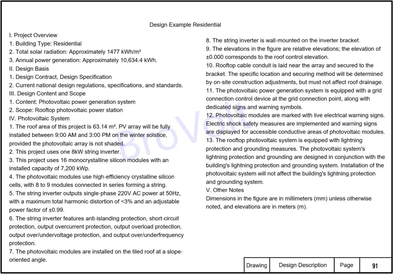
I. Project Overview
1. Building Type: Residential
2. Total annual solar radiation: Approximately 1477 kWh/m²
3. Annual power generation: Approximately 10,634.4 kWh.
II. Design Basis
1. Design Contract, Design Specification
2. Current national design regulations, specifications, and standards.
III. Design Content and Scope
1. Content: solar generator system
2. Scope: Rooftop solar generator system
IV. Solar Generator System
1. The roof area of this project is 63.14 m².Solar array will be fully installed between 9:00 AM and 3:00 PM on the winter solstice, provided PV array is not shaded.
2. This project uses one 8kW PV inverter.
3. This project uses 16 monocrystalline silicon modules with an installed capacity of 7,200 kWp.
4. Solar panels use high-efficiency crystalline silicon cells, with 8 to 9 modules connected in series forming a string.
5. PV inverter outputs single-phase 220V AC power at 50Hz, with a maximum total harmonic distortion of <3% and an adjustable power factor of ±0.99.
6.PV inverter features anti-islanding protection, short-circuit protection, output overcurrent protection, output overload protection, output over/undervoltage protection, and output over/underfrequency protection.
7. Solar panels are installed on the tiled roof at a slope-oriented angle.
8. PV inverter is wall-mounted on the inverter bracket.
9. The elevations in the figure are relative elevations; the elevation of ±0.000 corresponds to the roof control elevation.
10. Rooftop cable conduit is laid near solar array and secured to the bracket. The specific location and securing method will be determined by on-site construction adjustments, but must not affect roof drainage.
11. Solar generator system is equipped with a grid connection control device at the grid connection point, along with dedicated signs and warning symbols.
12. Solar panels are marked with live electrical warning signs. Electric shock safety measures are implemented and warning signs are displayed for accessible conductive areas of photovoltaic modules.
13. The rooftop solar generator is equipped with lightning protection and grounding measures. Solar generator lightning protection and grounding are designed in conjunction with the building's lightning protection and grounding system. Installation of PV system will not affect the building's lightning protection and grounding system.
V. Other Notes
Dimensions in the figure are in millimeters (mm) unless otherwise noted, and elevations are in meters (m).
Residential Solar Generator System
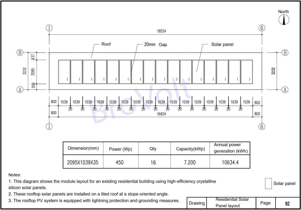
Residential Solar Panel Layout
Notes:
1. The aluminum rails and module clamps shown in this image are made of 6063-T5. The surface is anodized, with an oxide film thickness of no less than 15µm.
2. Solar pane clamps shown in this image use M8x45 hexagon socket bolts consisting of: 1 M8x45mm hexagon socket screw + 1 M8 wing-shaped nut + 1 flat washer + 1 spring washer + 1 grounding conductive washer.
3. All bolts are 304 stainless steel, grade A2-70. Ensure bolts are tightened during installation to prevent loosening of the solar panels.
4. During installation, rooftop fall protection measures must be implemented.
5. The cross-section of solar mounting system shown in the figure is for reference only. The specific cross-section is subject to manufacturer's specifications.
The original roof must be inspected by a qualified third-party organization. If it does not meet the requirements, it must be reinforced to meet the load requirements before installation of the rooftop solar generator system can begin
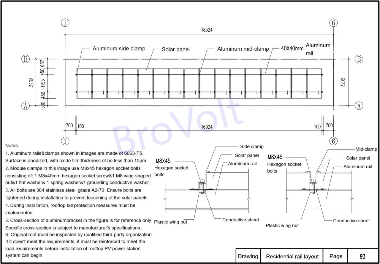
Residential Rail Layout
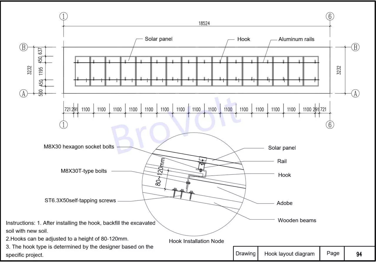
Hook Layout Diagram
Instructions
1. This diagram shows the wiring of solar panels.
2. After completing the wiring, check to see if the positive and negative are mixed up.
3. After connections are complete, measure PV array voltage and distinguish positive and negative of two sets of cables at the end of one bracket.
4. If solar panel junction box is located in the middle and it is unavoidable to install and connect the panels simultaneously, be sure to adjust the positive and negative of the panel junction box to avoid reverse connection and wasted intermediate wiring.
5. MC4 connectors are used to connect the positive and negative poles of the panels, with an IP67 rating. They must not be placed on rooftops or on the ground. Steel tie wraps should be used to secure the back of the panels. MC4 connectors must not be left hanging in the air to avoid contact with conductive objects. MC4 connectors must not be placed inside fender tubes.
6. If the built-in cable length is insufficient, additional photovoltaic cables and MC4 connectors are required to connect the panels. The MC4 connectors of the connecting wires should be of the same brand and model as the modules. For construction safety reasons, the cables and MC4 connectors connecting photovoltaic modules are not suitable for on-site construction. They should be processed into standard parts at the corresponding production factory according to the actual length on site (with sufficient cable length reserved) to achieve quick installation on site and avoid on-site operation.
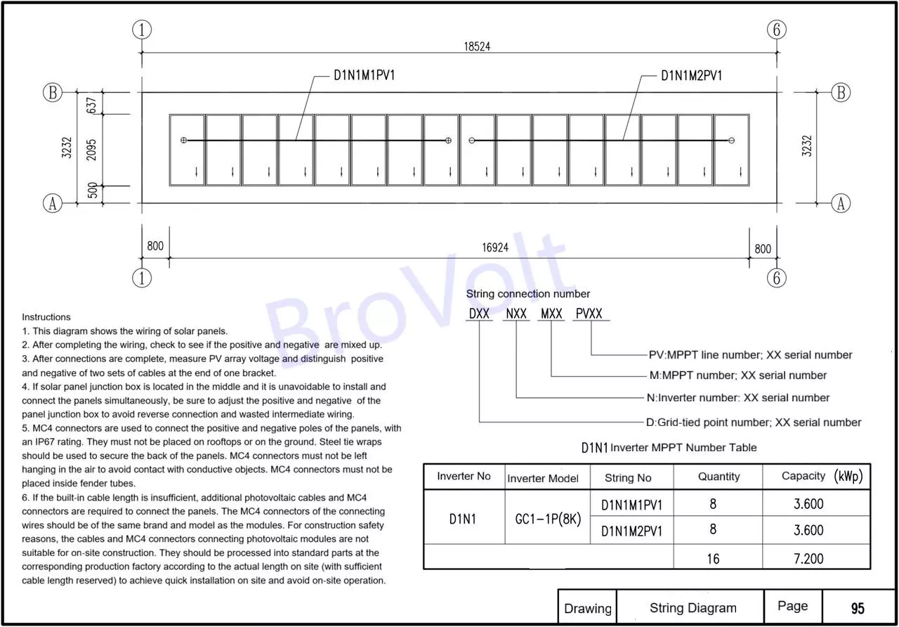
Solar Panel String Diagram
Notes:
1. All metal enclosures that are not normally live must be connected to the equipotential bonding. Metal enclosures of equipment such as inverter distribution boxes must be connected to the grounding terminal box using BVR-16mm or larger wires.
2. Metal frames of solar panels must be securely connected to solar mounting system using compressed lightning protection grounding gaskets.Solar mounting system must also be securely connected to the 40x4mm hot-dip galvanized flat steel grounding grid.
3. Metal pipes must be securely connected to the 40x4mm hot-dip galvanized flat steel grounding grid. Cable ducts and mounts must be connected to the grounding wire at at least two locations throughout the site.
4. Aluminum alloy cable trays must be securely grounded using grounding gaskets.
5. If the on-site building does not have a grounding grid, an independent grounding grid must be installed for this project.
6. Grounding electrodes must be tested to ensure the grounding resistance is no greater than 40° and no greater than the overall building resistance
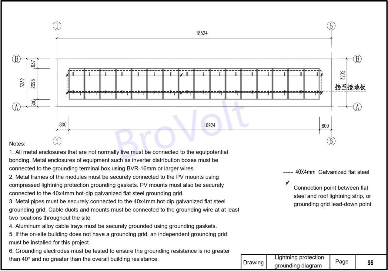
Lightning Protection Grounding Diagram