This project introduces the design of a rooftop solar photovoltaic (PV) power system for an office building. With the increasing demand for clean energy and the implementation of carbon reduction policies, rooftop PV systems have become an essential solution for urban buildings to achieve green and sustainable development. By installing high-efficiency PV modules and a grid-connected inverter system on the office building roof, the project maximizes the use of idle roof space, reduces electricity costs, and improves overall energy efficiency. The solar power system is designed in compliance with national PV standards and building safety codes, with a service life of 25 years. It provides a reliable and economical rooftop solar solution, offering valuable reference for office building PV system design and grid-connected solar projects.
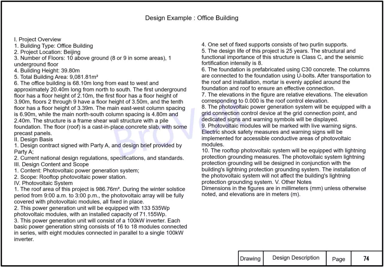
I. Project Overview
1. Building type: Office building
2. Project Location: Beijing
3. Number of building floors: 10 floors above ground (with some areas having 8 or 9 floors), and 1 floor underground.
4. Building height: 39.80 m;
5. Total floor area: 9,081.8㎡
6. The total length of the office building running east-west is 68.10 m, and the total length running north-south is approximately 20.40 m. The height of the first basement floor is 2.10 m, that of the first floor is 3.90 m, that of the second to ninth floors is 3.50 m, and that of the tenth floor is 3.39 m. The main column spacing for the east-west direction is 6.90m, and for the north-south direction, it is 4.80m and 2.40m respectively. The structural form is a frame-shear wall structure, and the foundation form of this structure is pile foundation. The floor (roof) is a cast-in-place concrete slab, with some parts being prefabricated slabs.
Ii. Design Basis
1. The design contract signed with Party A and the design assignment provided by Party A
2. Current relevant national design regulations, norms and standards.
Iii. Design Content and Scope
1. Content: Photovoltaic power generation system
2. Scope: Rooftop photovoltaic power stations.
Iv. Photovoltaic Systems
The roof area of this project is 986.76 ㎡. During the period from 9 a.m. to 3 p.m. on the Winter Solstice, the photovoltaic modules will be fully laid under the condition that the photovoltaic array is not shaded, and the photovoltaic modules will be installed in a fully fixed manner.
2. This power generation unit is equipped with 133 photovoltaic modules of 535Wp, with an installed capacity of 71,155Wp. 3. This power generation unit consists of one 100kW inverter. Every 16 to 18 battery modules are connected in series to form a basic power generation series, and 8 series of modules are connected in parallel to one 100kW inverter.
4. A set of fixed supports consists of two purlin supports. 5. The reasonable service life of this project is designed to be 25 years. The structural and functional importance category of this structure is Class C, and the seismic fortification intensity is 8 degrees. 6. The foundation is made of prefabricated blocks, using C30 concrete. The columns are connected to the foundation through U-bolts. After being transported to the roof for installation and placement, mortar is applied evenly around the foundation and on the roof to make effective connections.
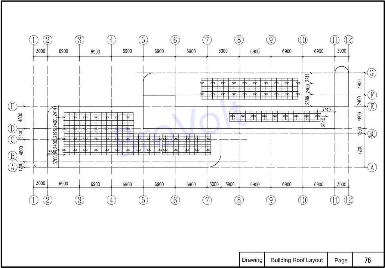
7. The elevation marked in the diagram is the relative elevation, and the elevation corresponding to ± 0.000 is the roof control elevation.
8. At the grid connection point of the photovoltaic power generation system, a grid connection control device is set up, along with dedicated identification and prompt text symbols.
9. Solar panels are marked with live warning signs. Electric shock safety protection measures should be taken and warning signs should be set up for the conductive parts of photovoltaic modules that can be reached by personnel :
10. Lightning protection and grounding measures should be set up for the roof photovoltaic system. The lightning protection and grounding of the photovoltaic system should be designed in combination with the lightning protection and grounding system of the building. After installing the photovoltaic system, it will not affect the lightning protection and grounding system of the building.
V. Other Explanations
Unless otherwise specified, the units of dimensions in the figure are all millim (mm), and the elevations are all m (m)
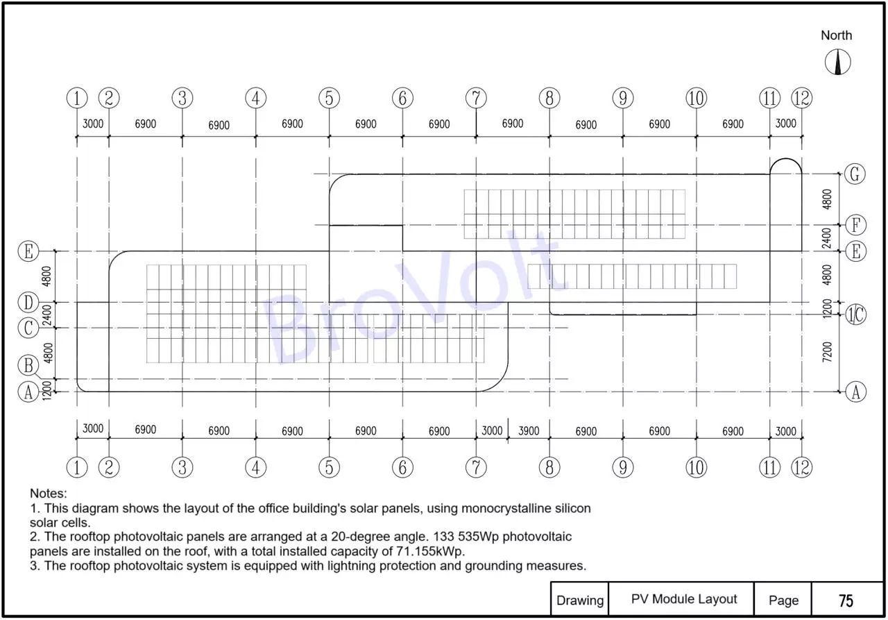
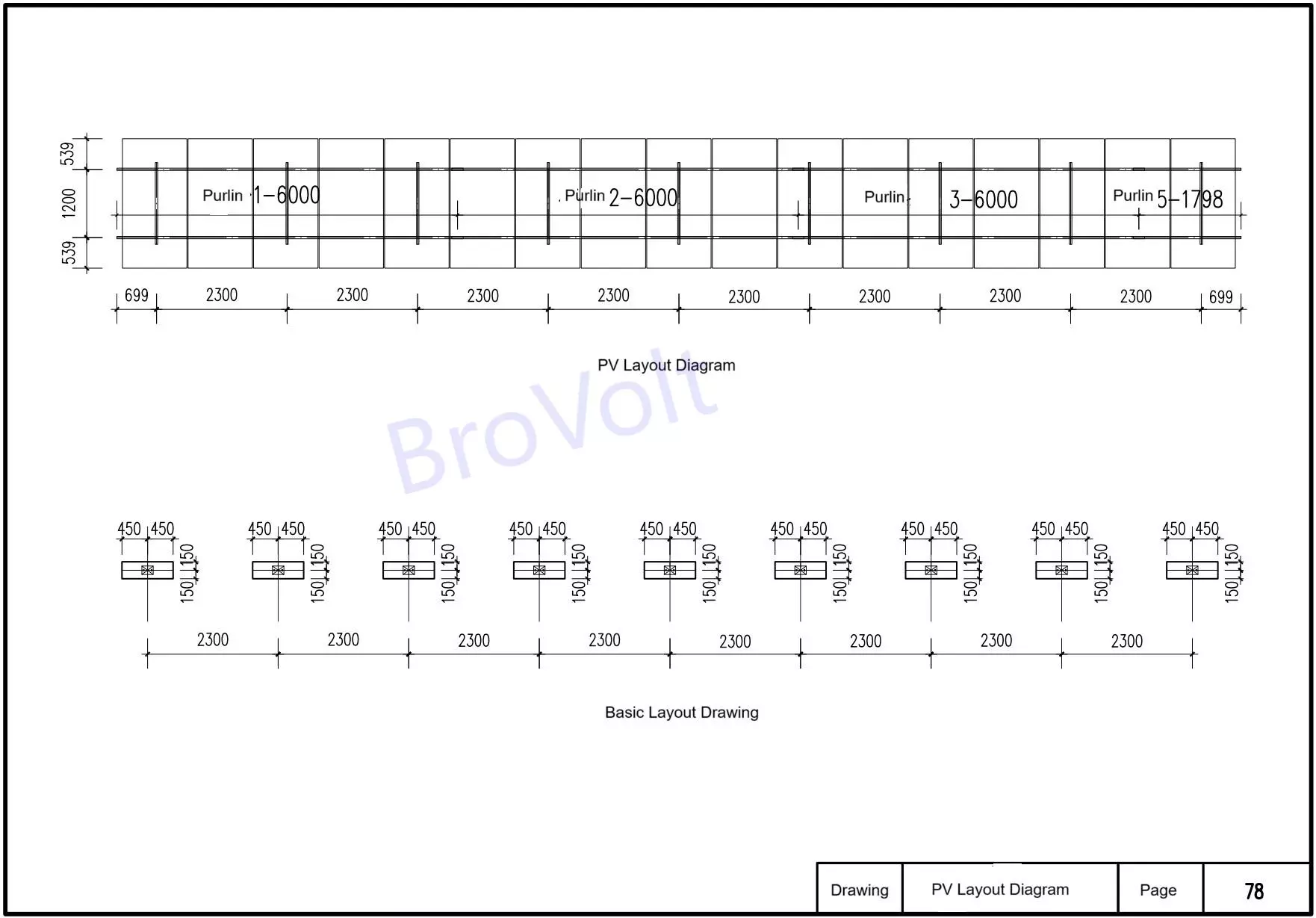
PV Module Layout
Building Roof PV Module Layout
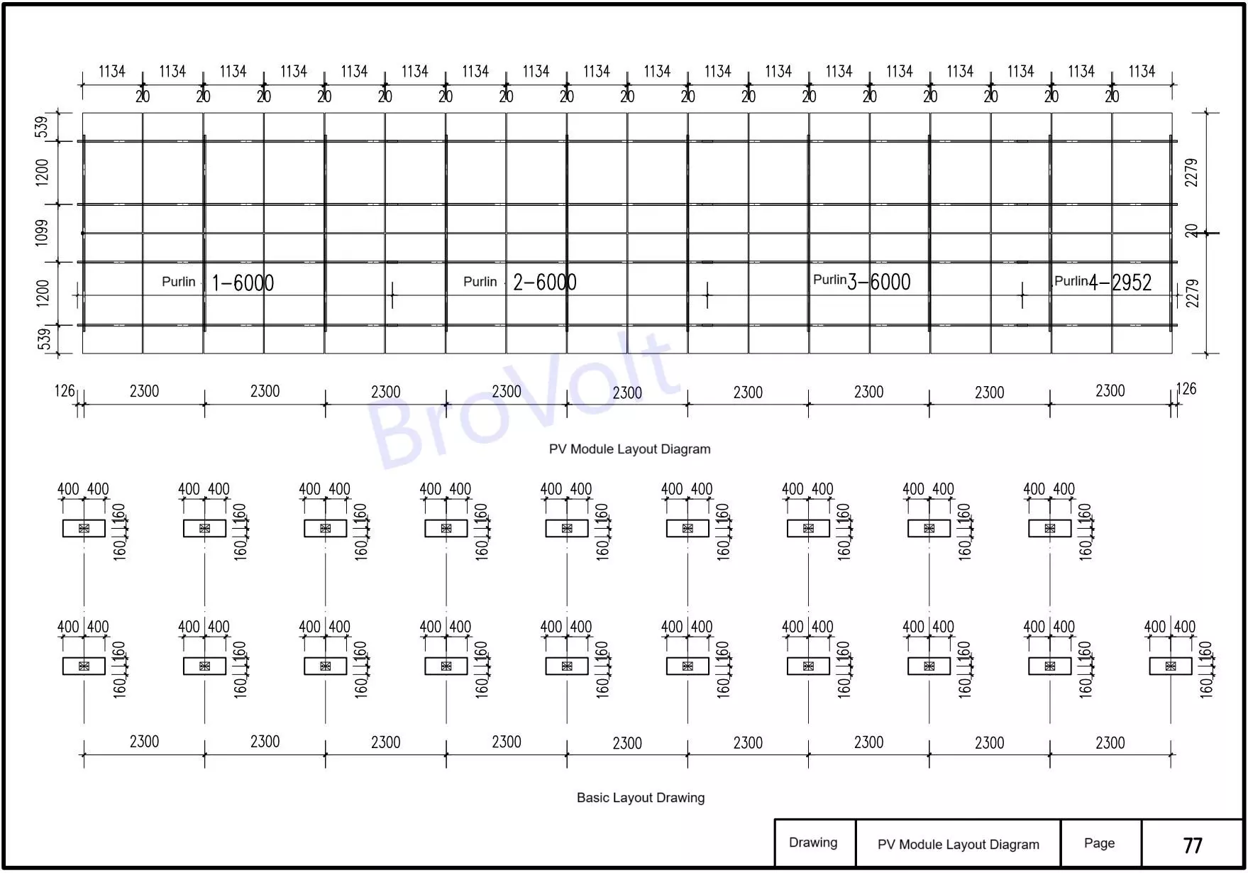
PV Module Layout Diagram
PV Module Layout Diagram
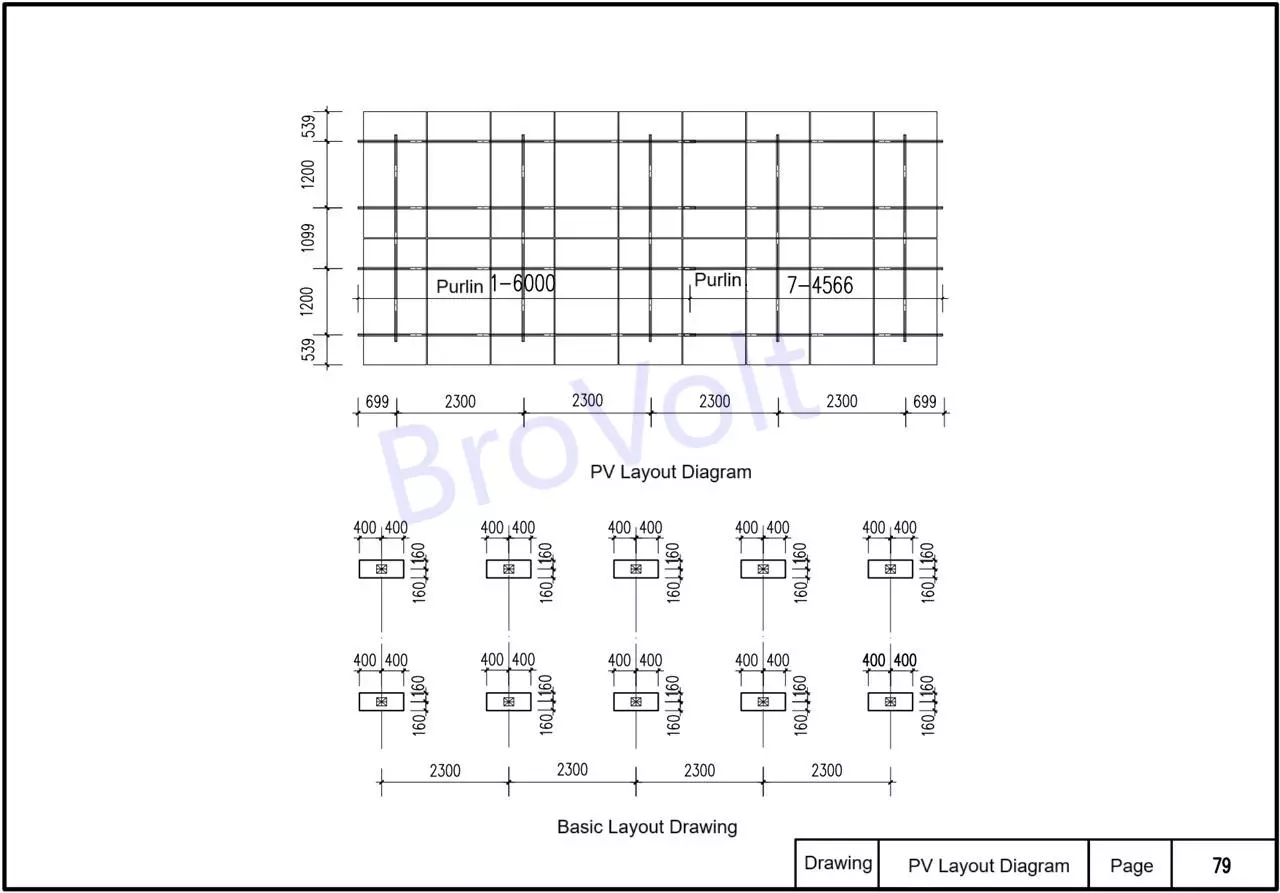
PV Module Layout Diagram
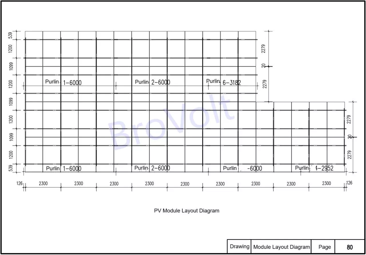
PV Module Layout Diagram
PV Module Layout Diagram
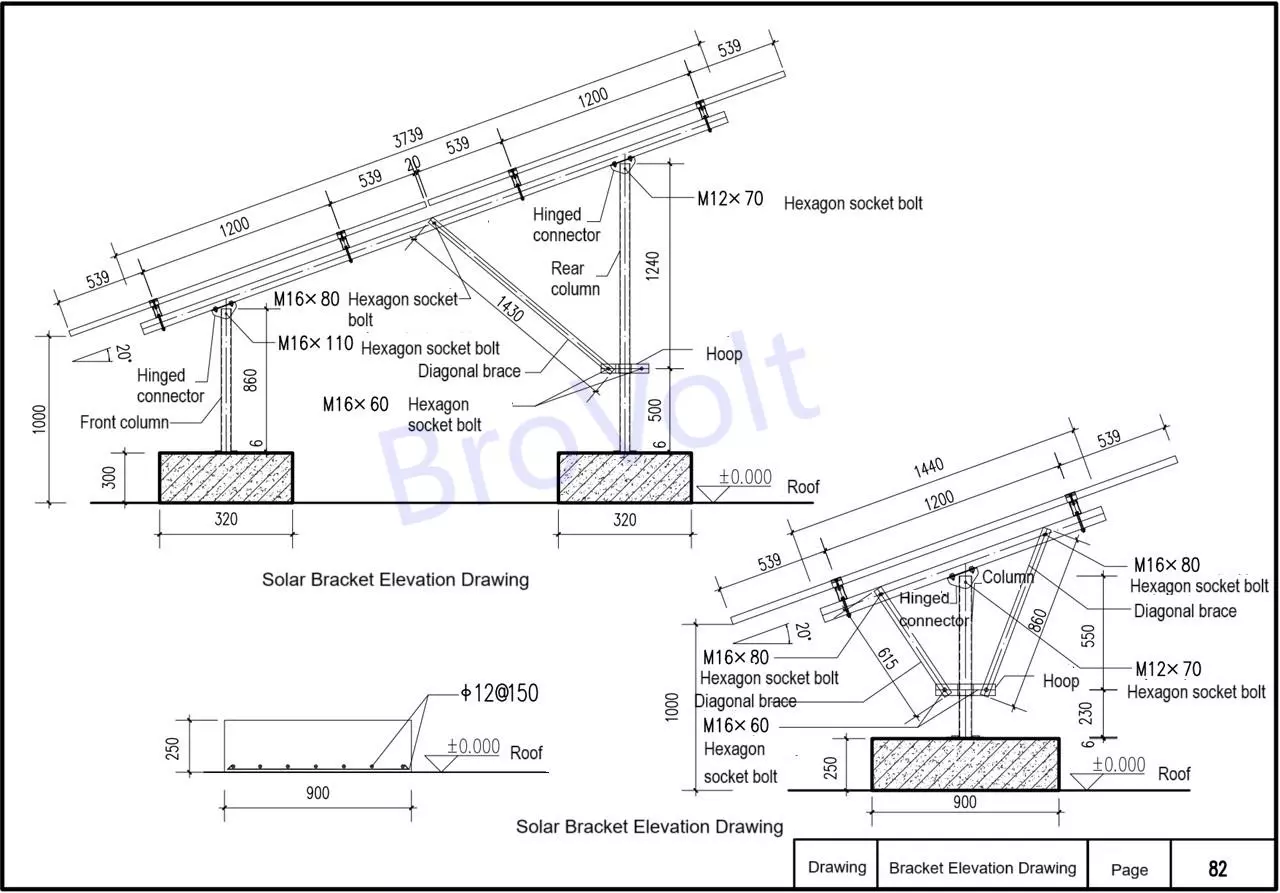
Solar Bracket Elevation Drawing
Explanation
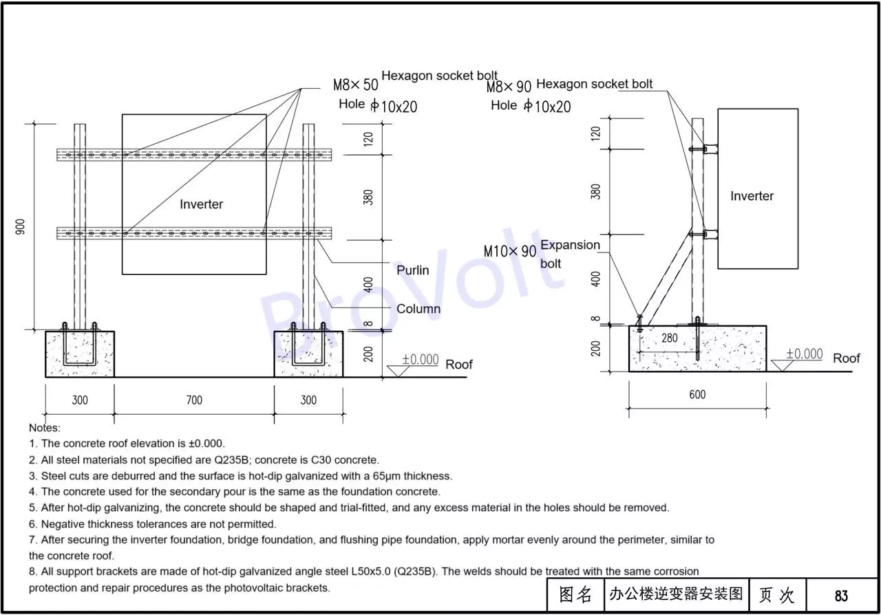
The elevation of the concrete roof is ± 0.000.
2. Unless otherwise specified, all steel materials are selected as Q235B. The concrete is C30 concrete.
3. Deburring of steel structure cuts, surface hot-dip galvanizing, galvanized layer thickness 65μm;
4. The concrete used for secondary pouring is the same as that for the foundation concrete:
5. After hot-dip galvanizing, it should be shaped and test-assembled to remove any excess substances in the holes.
6. Negative tolerance in thickness is not allowed.
7. After the inverter foundation, bridge frame foundation and cleaning water pipe foundation are fixed, apply mortar evenly around the concrete roof.
8. All support brackets are made of hot-dip galvanized Angle steel L50x5.0(Q235B), and the anti-corrosion repair at the welding points is the same as that of the solar brackets.
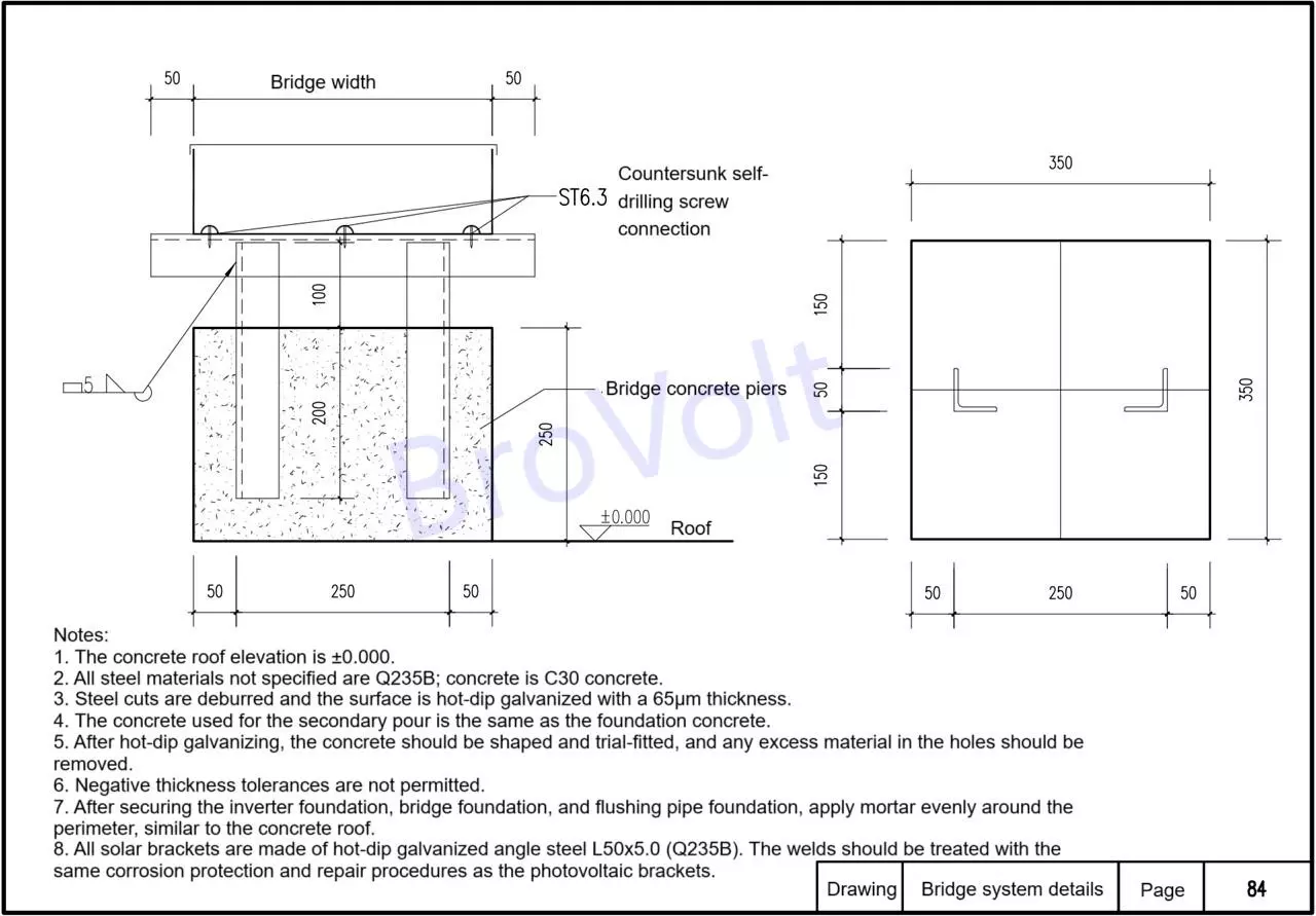
Solar Bridge System
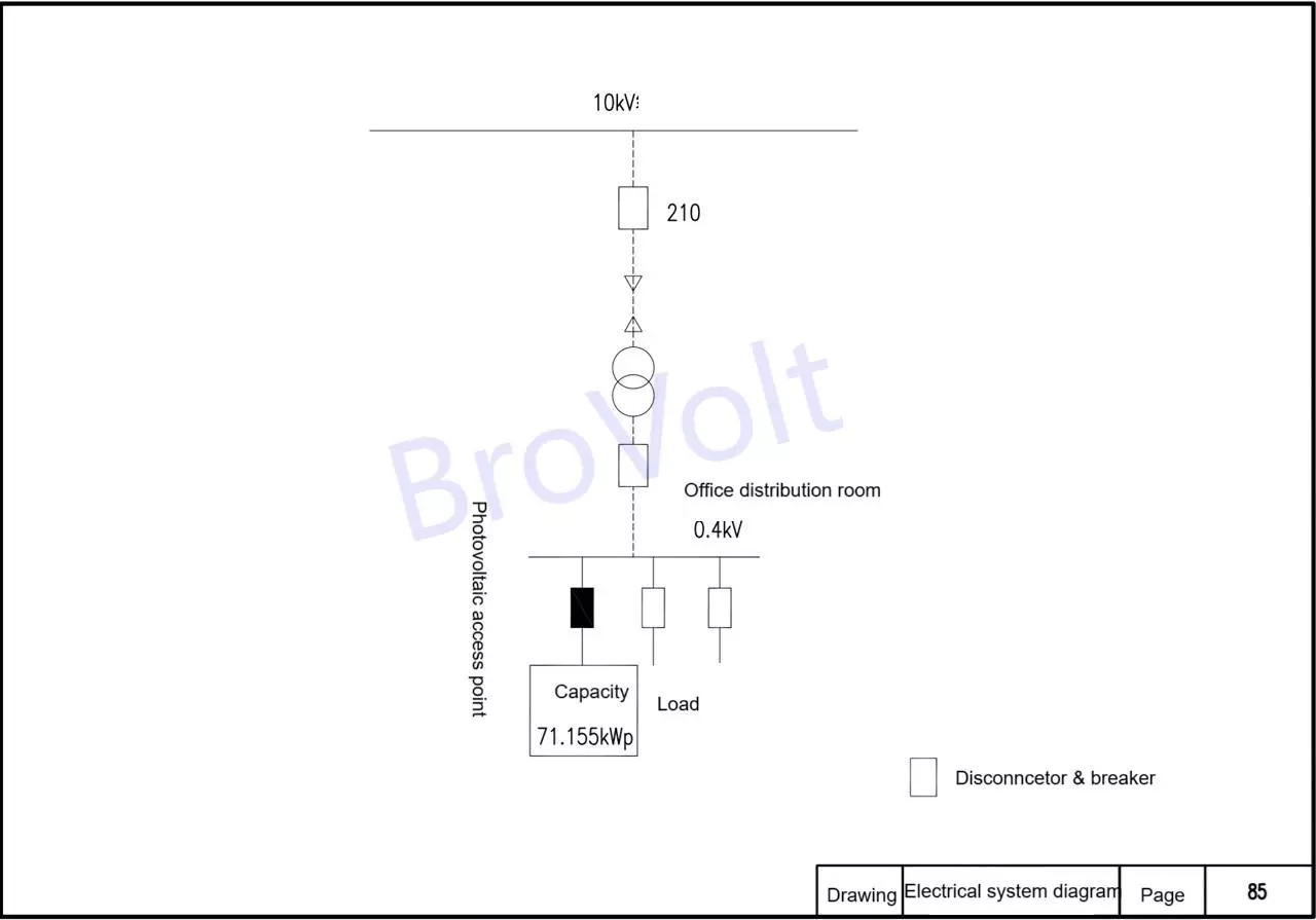
Electrical System Diagram

PV String Wiring Diagram
Notes:
1. MC4 connectors must not contact the roof, must not be fixed to the PV rack rails, or bundled with the PV cables. MC4 connectors must be suspended in the air or placed in conduit (do not overload the cable when suspended).
2. Inter-string cables and extension cables must not contact the roof and must be laid through conduit. The conduit must be fixed to the module frame or rails.
3. Because the built-in cable length of the modules is insufficient, additional PV cables and MC4 connectors are required to connect between PV modules. For safety and convenience reasons, MC4 connectors for PV modules are not suitable for on-site fabrication and installation. They should be manufactured into standard components (with sufficient cable length reserved) at the appropriate manufacturer based on the actual length on site. This allows for quick installation on-site, avoiding on-site fabrication.
4. Inter-module cables and extension cables must not contact the roof and must be secured to the module frame with cable clamps. When securing the cables, ensure the clamps are tight enough to prevent them from slipping out.
5. Strings connected to the same MPPT must be oriented in the same direction and have the same number of modules.
6. Cable labels indicating the string number must be attached to both ends of each PV string's outgoing PV cable.
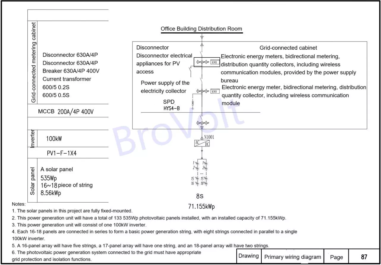
Primary wiring diagram of grid connection point
Note:
1. Solar panels in this project are fully fixed-mounted.
2. This power generation unit will have a total of 133 535Wp solar panels installed, with an installed capacity of 71.155kWp.
3. This power generation unit will consist of one 100kW inverter.
4. Each 16-18 panels are connected in series to form a basic power generation string, with eight strings connected in parallel to a single 100kW inverter.
5. 16 panels will be grouped into five strings, 17 panels into one string, and 18 panels into two strings.
6. The grid-connected photovoltaic power generation system must have appropriate grid protection and isolation functions.
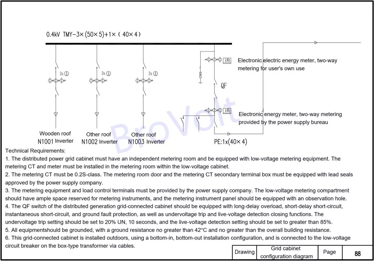
Grid Cabinet Configuration Diagram
Technical Requirements:
1. The distributed power grid cabinet must have an independent metering room and be equipped with low-voltage metering equipment. The metering CT and meter must be installed in the metering room within the low-voltage cabinet.
2. The metering CT must be 0.2S-class. The metering room door and the secondary terminal box of the metering CT must be equipped with lead seals approved by the power supply company.
3. The metering equipment and load control terminals must be provided by the power supply company. The low-voltage metering room should have ample space reserved for metering instruments, and the metering panel should be equipped with an observation hole.
4. The QF switch in the distributed generation grid-connected cabinet should be equipped with long-delay overload, short-delay short-circuit, instantaneous short-circuit, and ground fault protection, as well as undervoltage trip and live-voltage detection closing functions. The undervoltage trip setting should be set to 20% UN, 10 seconds, and the live-voltage detection setting should be set to greater than 85%.
5. All equipment and structures should be well grounded, with a ground resistance no greater than 4Ω and no greater than the overall building resistance.
6. This grid-connected cabinet is installed outdoors, using a bottom-in, bottom-out installation configuration, and is connected to the low-voltage circuit breaker on the box-type transformer via cables.
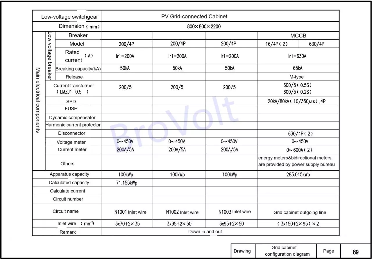
Grid Cabinet Configuration Diagram
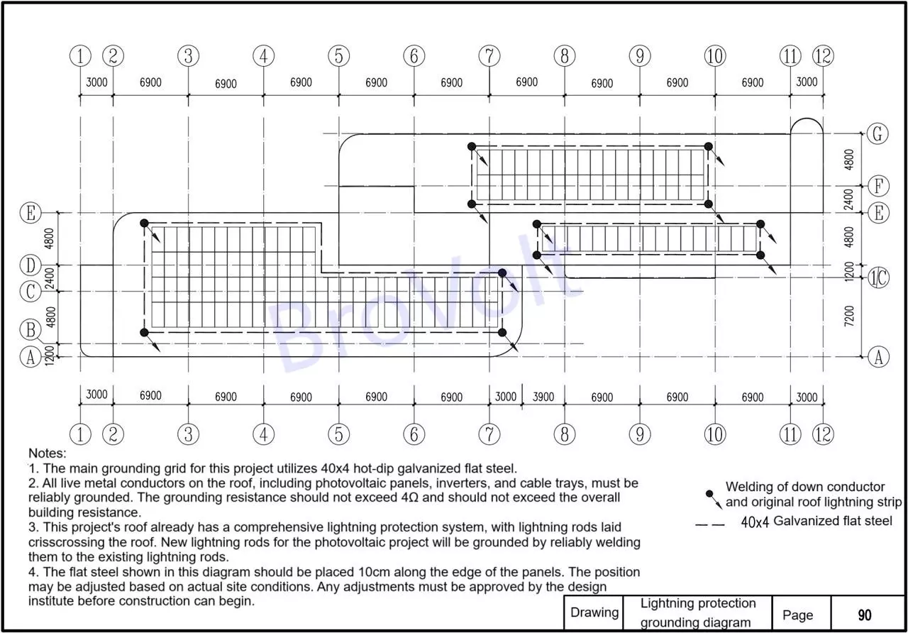
PV Array Lightning Protection Grounding Diagram
Notes:
1. The main grounding grid for this project utilizes 40x4 hot-dip galvanized flat steel.
2. All live metal conductors, including rooftop photovoltaic panels, inverters, and bridges, must be reliably grounded. The grounding resistance should not exceed 4Ω and should not exceed the overall building resistance.
3. This project's roof already has a comprehensive lightning protection system, with lightning rods laid crisscrossing the roof. New lightning rods for the photovoltaic project will be grounded by reliably welding them to the existing ones.
4. The flat steel shown in this diagram should be placed 10cm along the edge of the panels. The position may be adjusted based on actual site conditions. Any adjustments require approval from the design institute before construction can begin.