I. Introduction to Off-Grid Solar Power Systems
1.1 Introduction
An off-grid solar power system is a standalone power generation system that operates independently of the power grid. It primarily consists of solar panels, energy storage batteries, an inverter, and a load.
It uses photovoltaic modules to convert solar energy into electricity and stores it in batteries. When solar power is insufficient or at night, the batteries supply power to the load, achieving a self-sufficient energy supply.
This system is particularly suitable for areas without grid coverage, with unstable power supply, or in remote areas, such as rural areas, islands, telecommunication base stations, farms, pastoral areas, and emergency power supply scenarios.
1.2 Load parameters
User load parameters
| No | Home Appliance | Power(W) | Qty | Total Power(W) | Time(h) | Energy(Wh) |
| 1 | Light | 15 | 4 | 60 | 2 | 120 |
| 2 | Air Conditioner | 1000 | 2 | 2000 | 2 | 4000 |
| 3 | Washing Machine | 200 | 1 | 200 | 1 | 200 |
| 4 | TV | 200 | 1 | 200 | 4 | 800 |
| 5 | Laptop | 100 | 2 | 200 | 4 | 320 |
| 6 | Hair Dryer | 1000 | 1 | 1000 | 0.2 | 200 |
| 7 | Rice Cooker | 900 | 1 | 900 | 0.5 | 450 |
| 8 | Micro-wave Oven | 1100 | 1 | 1100 | 0.15 | 165 |
| 9 | Refrigerator | 150 | 1 | 150 | 8 | 1200 |
| 10 | Total | 5660 | 7455 | |||
| We calculate based on customer's appliance simultaneous usage rate of 0.8.Total power 6060W*0.8=4528W | ||||||
2. Relevant Regulations and Standards
The following standards may be used as references for the manufacture, testing, and acceptance of off-grid photovoltaic energy storage systems:
GB/T 18479-2001 "Guidelines for Ground-Based Photovoltaic (PV) Power Generation Systems"
GB/T 20046-2006 "Grid Interface Characteristics of Photovoltaic (PV) Systems"
GB2297-89 "Terminology for Teravolt Energy Systems"
GB/T 18210-2000 "Field Measurement of IV Characteristics of Crystalline Silicon Photovoltaic Arrays"
GB/T 20514-2006 "Measurement Procedure for Efficiency of Power Conditioners in Photovoltaic Systems"
GB/T 20513-2006 "Photovoltaic System Performance Monitoring - Guidelines for Measurement, Data Exchange, and Analysis"
GBT 20047.1-2006 "Safety Qualification of Photovoltaic (PV) Modules - Part 1 - Structural Requirements"
GB/T 14285-2006 "Technical Specification for Relay Protection and Safety Automatic Devices"
GB4064-1984 "Guidelines for the Safety Design of Electrical Equipment"
GB/T 14549-1993 "Power Quality - Public Grid Harmonics"
DL5027-1993 "Typical Fire Protection Code for Power Equipment"
EN50178 "Electrical Equipment for Use in Power Installations"
3. System composition and principle
3.1 Composition of off-grid solar power generation system
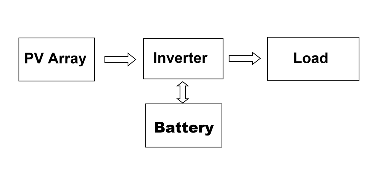
The PV off-grid solar power generation system mainly includes: solar array, battery, inverter, load, etc.
(1) Solar panel: Solar panel is the core part of the solar power generation system. Its function is to convert the radiation energy of the sun into electrical energy to supply power to the load.
(2) Inverter: The main function of the inverter is to convert direct current (DC) into alternating current (AC), so that the electricity stored in the battery or generated by the photovoltaic module can be used by ordinary electrical appliances or grid-connected systems.
(3) Battery: Generally a lithium ion battery. Its function is to store the electricity generated by the solar panel when there is sunlight and release it when needed.
(4) Bracket (5) System communication monitoring device;
(5) System lightning protection and grounding device;
(6) Civil engineering, power distribution box and other infrastructure;
(7) System connection cables and protective materials.
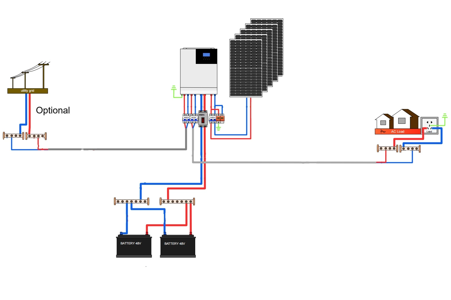
3.3 Schematic Diagram of an Off-Grid Photovoltaic System
The following diagram shows the schematic diagram of an off-grid system:
4. Off-grid power generation system design process
4.1 Solution introduction
The system uses an off-grid inverter and converts DC power into AC power through the inverter to supply the load.
4.2 Specific usage requirements
(1) Required continuous use of rainy days: 3 days;
(2) Load type: 220VAC;
(3) Daily power consumption:
According to the power consumption table of the user's electrical equipment, assuming that the total power of the user's electrical equipment is 6060W, based on an 80% simultaneous usage rate, the total power of the electrical equipment is 4848W, and the average daily power consumption is 8255Wh.
4.3 Battery design and selection
The battery capacity calculation is based on the system's daily power consumption, self-sufficient days, inverter efficiency, and battery discharge depth. Battery capacity is one of the key issues of a home solar photovoltaic system.
Battery Capacity Calculation:
Capacity = (QL ×D) / (η1 ×η2 ×η3) = (7.5 kWh ×3) / (0.95 ×0.9 ×0.92) = 28.6 kWh
QL: Average daily power consumption;
D: Number of consecutive rainy days, 3 days;
η1: Battery depth of discharge, 0.95;
η2: Inverter efficiency, 0.9;
η3: Battery discharge efficiency, 0.92;
Using two 51.2V 314Ah batteries in parallel, the total is 2 * 51.2V * 314Ah = 32.2 kWh, which can meet customer needs.
| Brand | Brovolt |
| Cell Type | LiFePO4 |
| Nominal Voltage | 51.2V |
| Capacity | 314Ah |
| Energy | 16.07kWh |
| Operating Voltage | 43.2V-58.4V |
| Operating Temperature | 0 ℃~55 ℃ |
| Charging Current | 140A |
| Discharing Current | 140A |
| Cycle Life | Cycle Life >6000(@25℃, 80%DOD) |
| Weight | 130kg |
| Dimension | 555*300*847mm |
4.4 Solar panel design and selection
(1) Design calculation of tilt and azimuth
The design of the horizontal tilt of solar panles mainly depends on the latitude of the PV power generation system and the requirements for the distribution of power generation throughout the year.
1) For the situation where the power generation is basically balanced throughout the year, the module tilt can be selected as follows:
Latitude 0~25° Tilt equals latitude
Latitude 26~40° Tilt equals latitude plus 5~10°
Latitude 41~55° Tilt equals latitude plus 10~15°
Latitude >55° Tilt equals latitude plus 15~20°
2) In most parts of China, the module horizontal tilt of 7° can usually be used.
For the situation where more power generation is required in winter, the module horizontal tilt of 11° can be used.
For the situation where more power generation is required in summer, the module horizontal tilt of 11° can be used. This off-grid power generation system is located at 30° north latitude. Considering the use of a balanced power generation mode throughout the year, the module inclination angle is temporarily set to 30°.
(2) PV Array spacing design calculation
Design of the spacing between the front and rear rows of the photovoltaic array or the spacing between the front obstruction:
If the spacing between the front and rear rows of the photovoltaic array or the spacing between the front obstruction is not designed properly, it will affect the power generation of the photovoltaic system, especially in winter.
The design of the spacing between the front and rear rows of the PV array or the spacing between the front obstruction is related to the latitude of the PV system and the height of the front row of arrays or the obstruction. The calculation formula is:
D = 0.707H / tan [arc sin (0.648cosΦ - 0.399sinΦ)]
D: front-to-back spacing;
Φ: PV system latitude (positive in the Northern Hemisphere, negative in the Southern Hemisphere);
H: vertical height from the bottom edge of the rear PV panels to the top edge of the front obstruction;
Assuming the project location is approximately Φ = 30°, then
D = 0.707H / tan [arc sin (0.648cos30° - 0.399sinΦ30°)]
= 0.707H / tan [arc sin (0.648 × 0.866 - 0.399 × 0.5)]
= 0.707H / tan [arc sin (0.561 - 0.2)] = 0.707H / tan [arc sin (0.561 - 0.2)] sin0.361〕
=0.707H/tan21.2°=0.707H/0.388=1.8H
(2) PV Capacity
The customer requested to minimize costs, and our strategy was to fully charge the battery within three days. We used nine 640W solar panels.
The calculation is as follows:
Equivalent hours per day: 4.2h
System efficiency: 0.8
Daily power generation: 640W*4.2h*0.8*9=19353.6Wh
Daily consumption: 8255Wh
Surplus energy: 19353.6-8255=11099Wh
The battery can be fully charged within three days.
(4) Solar panel selection and parameters
Select LONGI monocrystalline silicon 640W solar panels
| Maximum Power (Pmax/W) | 640 |
| Open Circuit Voltage (Voc/V) | 49.52 |
| Short Circuit Current (lsc/A) | 16.38 |
| Voltage at Maximum Power (Vmp/V) | 40.78 |
| Current at Maximum Power (lmp/A) | 15.69 |
| Module Efficiency(96%) | 23.69 |
| Operational Temperature | -40'C-+85'C |
| PowerOutput Tolerance | 0-3% |
| Nominal Operating Cell Temperature | 45士2'℃ |
| Dimension | 2382×1134×30mm |
| Weight | 33.5kg |
4.5 Off-grid Inverter Selection
The main function of an inverter is to convert DC power into AC power. It should have the following features: high-voltage disconnect and recovery, low-voltage warning and recovery, low-voltage disconnect and recovery, short-circuit protection, reverse charge protection, temperature compensation, and a timer. The peak power of an inductive load at startup is 3-5 times the rated power. Here, we use a value of 3 times. The inverter must meet the instantaneous power requirements of all appliances during startup. Refrigerators and air conditioners are examples of inductive loads.
Inverter capacity calculation:
(Startup factor*Maximum power of inductive load + Resistive load power)= 2150 * 3 + 3360W = 9660W.
We choose an inverter with a rated power of 5000W and a peak power of 10000W. It can fully meet the needs of customers.
| Battery Voltage | 48VDC |
| Battery Type | Lithium ion battery |
| Normial Power | 5000W/5000VA |
| Output Voltage | 230VAC± 5% @ 50/60Hz |
| Surge Power | 10000W/VA |
| Max PV Power | 6000W |
| MPPT Operating Voltage | 120VDC-450DC |
| MPPT Input Current | 22A |
| Operating temperature | 0℃-55℃ |
| Protection Rate | IP20 |
4.8 Cable Design and Selection
A 5kWp module is connected to eight 640Wp modules. The system open circuit voltage is 400V; the short circuit current is 16.38A; the operating voltage is 320V, and the operating current is 15.69A.
(1) DC side:
1) Between each series string circuit of the PV array and the inverter: use 2.5mm² copper wire, with a current range of 10A~15A;
2) Between the inverter and the battery: use 25mm² copper wire, with a current range of 100;
(2) AC side
1) Between the inverter and the AC circuit breaker: use 10mm² copper wire, with a current range of 50A~65A;
2) Between the inverter and the AC load: use 10mm² copper wire, with a current range of 50A~65A;
4.9 Solar Mounting System
Because this off-grid power generation system is installed on a flat roof, the PV array bracket adopts a roof rail bracket, and the bracket inclination angle is set to 30 degrees.
4.10 Grounding and lightning protection
In order to ensure that the system can operate safely in severe weather such as thunderstorms, lightning protection measures must be taken for this system. The main aspects are as follows:
(1) The ground wire is the key to lightning protection and lightning protection. While carrying out the construction of the distribution room foundation and the solar cell array foundation, select a location with thick and humid soil nearby, dig a 2-meter-deep ground wire pit, use 40 flat steel, add resistance reduction agent and lead out the ground wire. The lead-out wire uses 35mm² copper core cable, and the grounding resistance should be less than 4Ω.
(2) Build a lightning rod near the distribution room, 10~15 meters high, and make a separate ground wire. The method is the same as above.
(3) Lightning rods can be made of 12mm round steel. If lightning strips are used, round steel or flat steel should be used. The diameter of the round steel should be ≥48mm and the thickness of the flat steel should not be less than or equal to 4mm.
(4) Down conductors should be made of round steel or flat steel. The diameter of the round steel should be ≥8mm and the cross section of the flat steel should not be less than 4mm².
(5) The voltage of the PV array cable entering the distribution room is DC400V. It should be buried in PVC pipe and protected by a lightning arrester. In addition, the bracket of the solar panel array should ensure good grounding.
(6) The AC output line of the inverter should be protected by a lightning protection box.
(7) Grounding device: Artificial vertical grounding body should be made of angle steel, steel pipe or round steel; horizontal grounding body should be made of flat steel or round steel. The diameter of the round steel should not be less than 10mm, the cross section of the flat steel should not be less than 100 mm², the thickness of the angle steel should not be less than 4mm, and the thickness of the steel pipe should not be less than 3-5mm. The buried depth of artificial grounding body in the soil should not be less than 0.5mm. It needs hot dip galvanizing anti-corrosion treatment. The welding place should also be treated with anti-corrosion and rust prevention.
VII. System Installation and Debugging
7.1 Installation and Inspection of Solar Panels
(1) The weight of a 640W photovoltaic module is approximately 33.5kg. This off-grid power generation system uses a total of 8 modules, with an installation area of approximately 7m².
(2) Pre-build the solar panel array frame column and check its horizontal levelness. Only when it meets the standard can the iron frame be assembled. Test the current and voltage of a single panel and install the solar panels after passing the test. Finally, check whether the grounding wire and the iron frame fasteners are tightened, whether the solar panel connector is in reliable contact, and whether the junction box and connector must be waterproofed. Check whether the no-load voltage of PV array is normal. This work should be completed by the technicians of the module provider.
(3) Issues to note when installing PV array:
1) The arrangement of the panels should mainly consider the number of series and parallel connections, and should not cause problems such as idle panels and waste. The number of arrays should be properly coordinated with the number of series and parallel connections to facilitate group wiring.
2) Heat dissipation must be considered for solar panels. During the hottest summer months, power loss due to elevated temperatures is significant, and ventilation ducts should be designed. Typically, a gap of 5 to 10 cm should be maintained between individual solar panel, and the solar array should also be 5 to 10 cm above the ground.
3) Dedicated maintenance access should be provided between panels in the photovoltaic array.
4) The installation of solar photovoltaic arrays should fully consider the load-bearing capacity of the building structure in which they are installed. The support points of the brackets must be absolutely located on the main beams of the building to avoid safety hazards or construction accidents.
5) If the installation of a solar array requires disrupting the roof structure, thorough investigation should be conducted to ensure that the installation is carried out without compromising the safety and waterproofing of the building.
6) If the entire system consists of multiple subsystems, the installation of the PV array should take into account the balance of each subsystem and the distance from the distribution room.
7) When installing PV modules, try to avoid strong winds to prevent unexpected hazards or damage to the personal safety of construction workers or the structure of the modules themselves due to strong winds.
(4) Basic requirements for the design of solar mounting system:
1) The design, production and manufacturing of solar brackets should follow the principles of material saving, low cost, durability and easy installation.
2) Solar mounting system should be made of steel or aluminum alloy materials, and their strength should be able to withstand the damage of a level 10 gale.
3) The metal surface of PV array bracket should be galvanized, aluminum-plated or painted with anti-rust paint to prevent rust and corrosion.
4) When designing solar photovoltaic array brackets, factors such as local latitude and sunshine resources should be considered. It is necessary to consider the degree of integration with the building itself, and on this basis, the structure of PV array's sun tilt and azimuth angle should be fully optimized and adjusted to fully receive solar radiation energy and increase the power generation of PV array.
5) The connectors of the solar bracket, including the connectors between the components and the bracket, the connectors between the bracket and the bolts, and the connectors between the bolts and the array field, should all be made of electroplated materials or stainless steel.
7.2 Installation of the overall control part
Refer to the requirements of the product manual, connect the solar panels, batteries, and inverters in the corresponding order, observe the various operating parameters of the inverter, and make corresponding records. Compare the actual operating parameters with the nominal parameters, analyze the differences, and prepare for future debugging.
7.3 Inspection and debugging
(1) According to the requirements of the on-site inspection, check whether the construction plan is reasonable and whether it can fully meet the requirements.
(2) According to the design requirements and the supply list, check whether the supporting components, equipment, instruments and equipment are complete as required and whether the supply quality meets the requirements. For some key equipment and materials required for some projects, sampling inspections can be carried out at the equipment and material manufacturer or delivery site according to relevant technical regulations and standards depending on the specific situation.
(3) On-site inspection and acceptance: Check whether the construction quality of the solar array cement foundation and distribution room meets the requirements and make records.
(4) Debugging is to test and adjust the parameters of the installed equipment in various working modes according to the equipment specifications. System commissioning must be conducted in accordance with the equipment's technical manual and relevant safety regulations. Upon completion, the system must meet or exceed the performance indicators specified in the equipment specifications. If actual performance discrepancies with the manual parameters are found during commissioning, the equipment supplier must take corrective measures. Only when the performance meets the standards will the system be eligible for acceptance.
8. Operation and Maintenance Precautions
8.1 Daily Maintenance
Preventive maintenance is the best maintenance, so the off-grid photovoltaic system should be inspected regularly. In this way, small problems can be discovered and dealt with before they become big problems. Most inspections can be performed using a voltmeter and an ammeter. Regular inspections can eliminate hidden dangers before the system fails. The following inspections should be performed:
(1) Maintenance of solar panels and brackets
1) Regular cleaning
Use a dry or damp soft clean cloth to wipe the surface of the module. It is strictly forbidden to use corrosive solvents or hard objects to wipe the surface of the module; the module should be cleaned when the irradiance is less than 200W/m². It is not advisable to use liquids with a temperature higher than that of the module to clean the module. 2) Regular Inspection
If any of the following problems are found, they must be adjusted or replaced immediately:
① Cracked glass, burnt backsheet, or noticeable color change on the solar panel;
② Bubbles forming a path between the solar panel and the module edge or any circuitry;
③ Deformed, twisted, cracked, or burned junction box, preventing proper connection of the terminals;
3) The live warning label on the solar panel must be intact;
4) For modules with metal frames, the frame and bracket must be well bonded, with a contact resistance of no more than 4Ω, and the frame must be securely grounded;
5) When operating under unshaded conditions, with a solar irradiance of approximately 500W/m² or higher and a wind speed of no more than 2m/s, the temperature difference on the surface of the same module (the area directly above the cells) must be less than 20°C.
6) Using a DC clamp-on ammeter, under conditions of essentially uniform solar irradiance, measure the input current of each PV module string connected to the same DC combiner box. The deviation should be no more than 5%.
7) All direct bolts, welds and bracket connections should be firm and reliable, and the surface anti-corrosion coating should not crack or fall off, otherwise it should be repaired in time.
2) Maintenance of the inverter
1) The structure and electrical connections of the inverter should be kept intact. Rust and dust accumulation are not allowed. The heat dissipation environment should be good. There should be no large vibration and abnormal noise during operation.
2) The warning signs on the inverter should be complete.
3) The radiator fans of the modules, reactors, and transformers in the inverter should start and stop automatically according to the temperature. There should be no large vibration and abnormal noise when the cooling fans are running. If there is any abnormality, the power should be turned off for inspection.
(3) Cable maintenance 1) The cable should not be operated under overload. The cable should not swell or crack. 2) The cable should be sealed at the entrance and exit of the equipment. There should be no gaps larger than 10mm. If there are holes, seal them with fireproof mud; 3) In the part where the cable exerts too much pressure or tension on the equipment casing, the cable support point should be intact;
4) The cable protection steel pipe mouth should not have perforations, cracks or significant unevenness, and the wall should be smooth; the metal cable pipe should not be seriously rusted, and should not have burrs, hard objects or garbage. If there are burrs, they should be smoothed and wrapped with cable jacket and tied tightly;
5) The accumulation of outdoor cable wells should be cleaned in time. If the cable sheath is damaged, it should be handled immediately;
6) When inspecting the open trench of the indoor cable, prevent damage to the cable and ensure that the bracket is grounded and the trench is well ventilated;
(4) Other maintenance
1) Check the tightness and firmness of all connections in the system. The battery connection should be clean and sealed with anti-corrosion agent.
2) Check whether all wire boxes are closed (sealed) to see if there is water damage and corrosion. If the electronic components are installed in the junction box, check the box air condition and replace or clean the air filter.
3) Check the operation of the switch to determine whether the switch is operating correctly. Check for corrosion and carbonization near the contacts.