1. Background and Significance
1.1 Project Background
With the gradual and comprehensive advancement of smart grid construction, and the continuous development of emerging elements such as distributed power sources, microgrids, the energy internet, and electric vehicles, the traditional distribution grid is undergoing significant changes and facing new challenges. These challenges include supporting the grid connection of large-scale renewable distributed energy generation and supporting interaction with users to adapt to the needs of electric vehicle development. The bidirectional power flow of these distributed generation devices posed a significant challenge to the grid. Electric vehicle charging power reaches hundreds of kilowatts, requiring the construction of dedicated charging facilities. Based on development trends, electric vehicle charging load will account for a large proportion of the total grid load in the future. However, the randomness of electric vehicle charging presents a significant power balancing resource for the grid. By implementing time-of-use pricing, users can be guided to actively adjust their electric vehicle charging times, significantly reducing peak-valley load differences and improving the utilization rate of existing grid capacity. Furthermore, it can effectively compensate for the intermittency of renewable power generation, reducing the demand for system reserve capacity. Therefore, the integration of distributed renewable energy and the development of electric vehicles are necessary for the development of a low-carbon economy and energy conservation and emission reduction; their development trend is undeniable. In the long run, future microgrids will develop towards higher reliability, better power quality, and adaptability to the needs of distributed new energy access and electric vehicle charging and swapping. Advanced measurement systems, more cost-effective communication networks, and intelligent integrated control scheduling and energy management systems will play an important role in improving the production management level and power supply reliability of microgrids, and will deepen the construction of smart grids.
1.2 Project Significance
This project is a microgrid demonstration project covering wind, solar, energy storage, charging, and utilization. Through the construction of the project, it explores the establishment of a local power system integrating generation, transmission (distribution), storage, and utilization that can accommodate a high proportion of fluctuating renewable energy power, and explores new business operation models and new forms of power energy services.
(1) Adapting to local conditions and innovating mechanisms. A grid-connected microgrid will be constructed based on the actual situation of the park and the development of new energy. New energy will be the main power supply mode for the microgrid. The project will explore technologies for independent power supply combined with the main power grid under the grid-connected mode, as well as new power grid marketing and management models under the grid-connected mode of new energy microgrids.
(2) Multi-energy complementarity and self-contained integration. The project combines various distributed energy sources, energy storage, and high-efficiency energy technologies, and through smart grids and energy management systems, forms a highly efficient integrated distributed energy system based on renewable energy.
(3) Advanced technology and economic rationality. The project integrates distributed energy and intelligent integrated power energy control technology to form an advanced and efficient energy technology system; it establishes a two-way interactive relationship with the public power grid, which can smooth the volatility of renewable energy, reduce the peak-valley difference of the power grid, replace or partially replace peak-shaving power sources, and can receive and execute power grid dispatch instructions; the exchange power and exchange time of the grid connection point are controllable, and it is conducive to the control of voltage and frequency within the microgrid; it ensures the continuous power supply of all local loads or important loads through off-grid and on-grid control; and it makes the new energy microgrid economically rational under certain policy support so that it can flexibly participate in the power market transaction in the future.
(4) Typical Demonstration, Easy to Promote. Based on existing conditions, the project fully explores the application of various distributed energy and microgrid technologies, innovates management systems and business models, integrates various policies, forms a typical model with local characteristics and easy replication, and gradually promotes it based on demonstration.
2. Project Status and Objectives
2.1 Basic Project Information
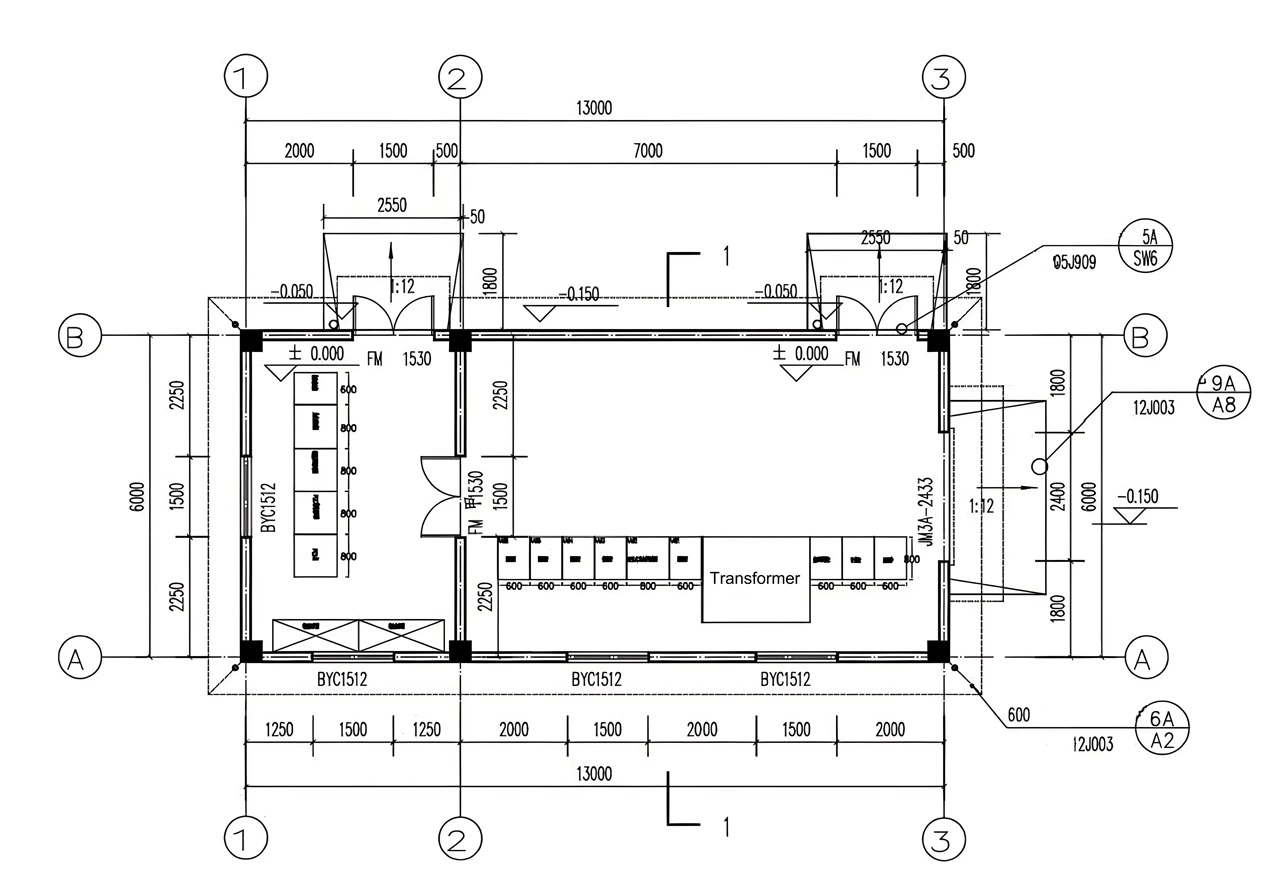
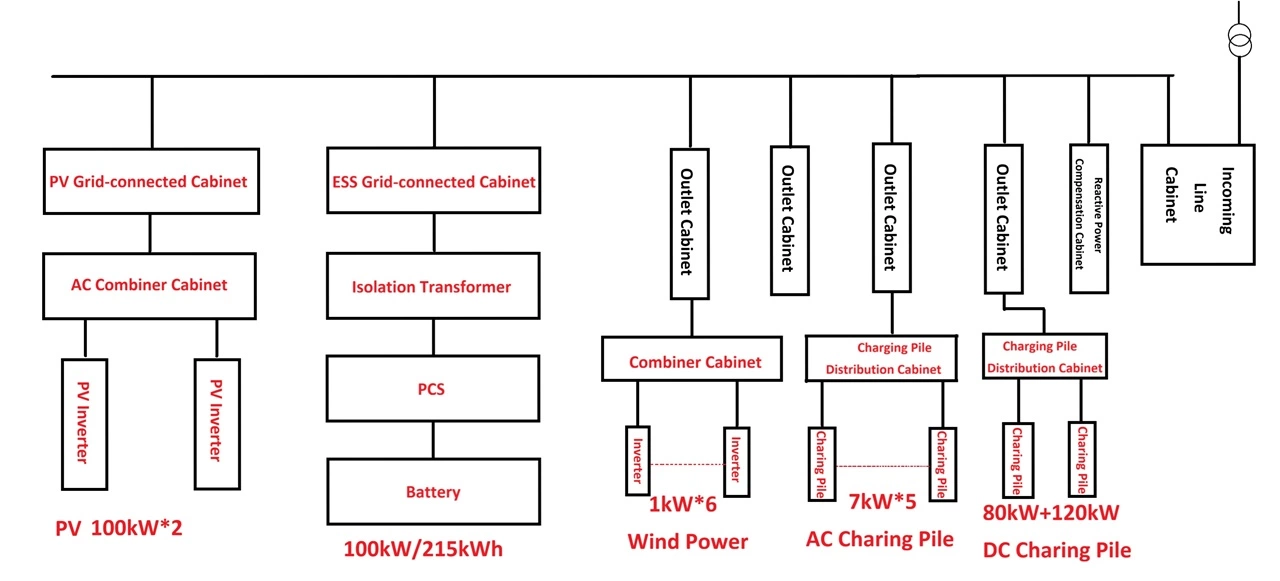
The project is equipped with a dedicated power distribution room. A 10kV incoming line is connected to the power distribution room, which contains one dry-type transformer, one incoming line cabinet, one reactive power compensation cabinet, and four feeder cabinets. The four feeder cabinets supply power to the office building, dormitory building, exhibition hall building, substation, outdoor landscape lighting, rooftop, fire protection, central computer room, elevators, etc. At the same time, space is reserved in the power distribution room for the subsequent installation of an energy storage system.
The system diagram is shown below:
The project site accepts a voltage level of 10kV, with an installed capacity of 500kVA and an annual electricity consumption of approximately 680MWh. The current power load of the research institute is 100kW, and considering future expansion, the average future load power is approximately 300kW.
Electricity charges are calculated based on transformer capacity, per-kilowatt-hour cost, and regulation factor cost, with the per-kilowatt-hour cost being a fixed price of 0.1USD/kWh.
Currently, no meters are installed on any of the electrical circuits or equipment. The total electricity consumption of the research institute can only be recorded manually from the main meter. There is no clear understanding of the power consumption status and energy flow of each circuit and piece of equipment. Electricity management methods are relatively primitive, and various electricity management regulations are inadequate. The application of energy-saving technologies is insufficient, indicating significant room for improvement and potential for energy conservation.
2.2 Meteorological Data
This project is located between 31°40′34” and 31°57′36” north latitude and 119°59′ and 120°34′30” east longitude. It borders the Yangtze River to the north. The climate is warm and humid year-round with favorable heat conditions. The average annual temperature is 15.7℃, with the average temperature of the hottest month in summer averaging 28.3℃. The average frost-free period is over 240 days per year, and sunshine is plentiful, with a sunshine percentage of 43%. July is the hottest month of the year, and January is the coldest. Common meteorological disasters include typhoons, torrential rains, continuous rainy days, and cold spells. Tides, hail, and strong winds are common. Sunshine hours are highest in July and August. Rainfall is abundant throughout the year, with an average of 136.6 rainy days and an average annual precipitation of 1177 mm. Rainfall is concentrated in spring and summer, resulting in abundant surface and groundwater.
2.3 Meteorological Impact Analysis
(1) Environmental Temperature Condition Analysis
Based on multi-year meteorological data from the local meteorological station, the multi-year average temperature of the project site area is 15.7℃, the multi-year extreme maximum temperature is 39.4℃, and the multi-year extreme minimum temperature is -14.2℃.
Therefore According to the extreme temperature data of the project site, the operating temperature of the solar panels in this project can be controlled within the allowable range. At the same time, the site temperature is relatively mild, which is beneficial for increasing the power generation of PV power generation system.
(2) Maximum Wind Speed and Sandstorm Impact Analysis
This project is unobstructed on all sides, with a maximum wind speed of 23.7 m/s. The solar panels have a large windward area, and the design of the module support must consider the impact of wind load. The basic principle is that the wind resistance of the solar panels support and foundation should not be damaged under 25 years of wind pressure.
(3) Snow Accumulation Impact Analysis
The selection of the distance H between the lowest point of the solar panel and the ground mainly considers the following factors:
a. Higher than the maximum local snow depth;
b. To prevent animal damage;
c. To meet the requirements of counterweight calculation;
Since there is no snow accumulation in this area, snow accumulation in the site area has no impact on the safety of the solar panels.
(4) Hail Disaster
The surface of the photovoltaic modules is tempered glass, and all have passed the photovoltaic module hail impact test, and can withstand the impact of ordinary hail.
3. Design Basis
GB/T 14549-1993 "Power Quality - Harmonics in Public Power Grids"
GB 50052-2009 "Code for Design of Power Supply and Distribution Systems"
GB50054-2011 "Code for Design of Low-Voltage Power Distribution"
GB50065-2011 "Code for Grounding Design of AC Electrical Installations"
GB50168-2006 "Code for Construction and Acceptance of Cable Lines in Electrical Installations"
GB 50169-2006 "Code for Construction and Acceptance of Grounding Devices in Electrical Installations"
GB 50217-2007 "Code for Design of Cables in Power Engineering"
Q/GDW 238-2009 "Code for Power Supply System of Photovoltaic Charging and Storage for Electric Vehicles"
GB_T_2297-1989 "Terminology of Solar Photovoltaic Energy Systems"
GB 50797-2012 "Code for Design of Photovoltaic Power Stations"
GB/T 20046-2006 "Characteristics of Grid Interface for Photovoltaic (PV) Systems"
GB/T 19939-2005 Technical Requirements for Grid Connection of Photovoltaic Systems
CECS85-96 Technical Specification for Construction and Acceptance of Solar Photovoltaic Power System Installation Engineering
GB/T 18287-2000 General Specification for Lithium-ion Batteries and Battery Packs
GB/T 2900.11-1988 Battery Terminology
GB51048-2014 Design Specification for Electrochemical Energy Storage Power Stations
Q/GDW 1885-2013 Technical Conditions for Energy Storage Converters in Battery Energy Storage Systems
NB/T 31016-2011 Technical Conditions for Battery Energy Storage Power Control Systems
4. Overall Scheme
4.1 System Topology
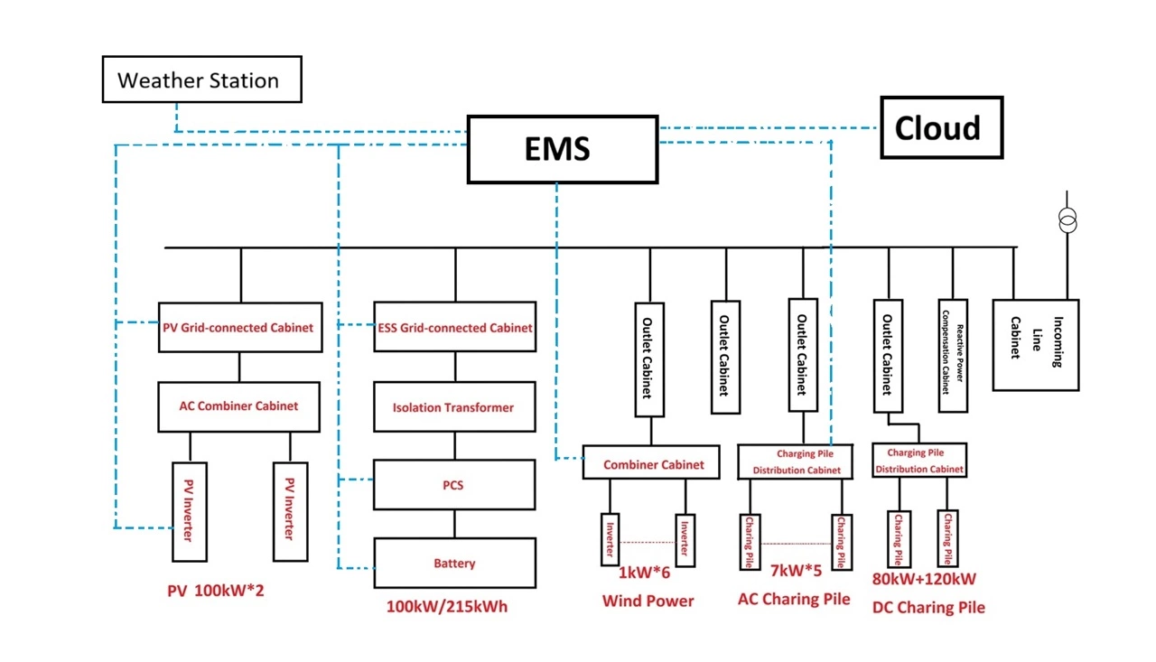
This upgrade mainly involves adding a photovoltaic power generation system, a wind power system, an energy storage system, charging piles, and related electricity metering devices to the existing system. The upgraded power distribution system diagram is shown below, with the red parts representing the new components.
Photovoltaic System: This project utilizes a 300kW photovoltaic system installed on the rooftop, forming the main source of new energy power generation. Due to the significant fluctuations in photovoltaic power generation caused by natural conditions, the microgrid control system should focus on monitoring and scheduling the photovoltaic power generation equipment.
Wind Power System: This project installs six 1kW small wind turbines, totaling 6kW, for wind power system research.
Energy Storage System: A 100kW/215kWh lithium ios solar battery is configured as the sole energy storage system for the microgrid. Its function is to regulate the performance of the micro-power source, ensure power quality for sensitive loads, suppress system oscillations, and perform peak shaving and valley filling. Local control and protection for each lithium solar battery are provided by a corresponding BMS, and the microgrid control system manages and controls the BMS via communication.
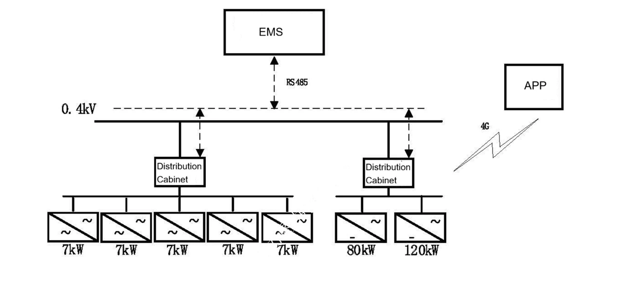
AC Charging Stations: This project includes five 7kW AC charging stations, one 80kW DC charging station, and one 120kW DC charging station. Local protection and control of these charging stations are handled by the charging station itself, while the microgrid control system manages and schedules the charging stations via communication.
4.2 System Features
This project will construct a multi-source microgrid system based on a 0.4kV AC bus, integrating mains power, photovoltaic power, wind power, energy storage, charging piles, and traditional loads. Through joint control of power generation and consumption within the microgrid, unified management and scheduling will be achieved, enabling dynamic management of the research institute's load and adjusting load protection levels according to equipment operating conditions.
To achieve the management, monitoring, and control of the entire microgrid system, the architecture of the project's monitoring system is shown in Figure 11.
(1) The system adopts a three-layer architecture: the top layer is the energy management system, the middle layer is the central control system, and the bottom layer is the equipment layer. This system is an autonomous system capable of self-control, protection, and management, and can switch between grid connection and off-grid operation. It can operate in parallel with the external power grid or in isolation.
(2) The system possesses comprehensive communication, monitoring, management, control, early warning, and protection functions, ensuring continuous and safe operation over long periods. The system's operating status can be monitored via a host computer, providing rich data analysis capabilities.
(3) The system's energy dispatch strategy is flexibly adjusted and set by the energy management system based on the SOC (State of Charge) of the lithium ion solar batteries.
(4) The system operates in parallel with the power grid, achieving economical operation and intelligent dispatch through the prediction of distributed power sources and loads.
5.1.1 Design Principles
PV power generation system design requires high reliability to ensure normal operation under harsh conditions; it also requires ease of operation and maintenance for user convenience.
Considering the special characteristics of rooftop PV and the safety and reliability of grid-connected systems during installation and use, while minimizing the connection lines between PV array and the inverter and facilitating future maintenance, string inverters are recommended.
PV power generation system should be rationally configured to reliably meet load requirements, minimizing system size and reducing investment costs.
5.1.2 System Scheme
This project is designed as a distributed system, without using sun-tracking or concentrating systems. Solar panels are installed at a fixed tilt angle and connected to the enterprise's low-voltage power distribution system to achieve "self-consumption and surplus power to the grid."
(1) Installed Capacity
Based on current load electricity consumption, electricity prices, installation location, and investment costs, the installed capacity of this project is determined to be 300kW. It is estimated that after commissioning, the overall self-consumption rate will reach over 90%.
(2)Tilt Angle Setting
The optimal tilt angle for fixed installation depends on many factors, such as geographical location, annual solar radiation distribution, the ratio of direct to diffuse radiation, load power supply requirements, and specific site conditions.
The installation tilt angle of PV array has a significant impact on the efficiency of the photovoltaic power generation system. For fixed array implementation, photovoltaic modules should be installed with appropriate azimuth and tilt angles to ensure optimal performance of the solar panels. The installation location should be chosen to ensure that the modules receive sunlight from 9:00 AM to 3:00 PM on the day with the shortest sunshine hours in the local year.
The optimal installation tilt angle is determined by the site latitude and the monthly distribution of solar irradiance. Based on the site's horizontal solar radiation data, the calculation method for the total solar radiation on the tilted surface can be optimized to obtain the optimal tilt angle.
This project involves installation on a corrugated steel roof. To minimize the additional load on the photovoltaic system, a fixed-tilt installation method is adopted. The tilt angle of the fixed brackets on the corrugated steel roof is approximately 3° relative to the roof's tilt angle. On the north-sloping roof, the angle is 3°after the brackets are raised.
The solar mounting systems are installed and fixed using specialized photovoltaic clamps that hold the corrugated steel roof tiles, without damaging the roof's waterproofing layer. On the south-sloping roof, the photovoltaic modules are directly installed with the roof's tilt angle aligned with the roof's angle. On the north-sloping roof, the horizontal tilt angle of the support columns is 3°after construction.
The bracket structure uses aluminum alloy profiles and is fixed with bolts. The bolts are made of 304 stainless steel, ensuring a service life of >25 years.
(3) Calculation of power generation
Based on the project's installed capacity, installation location, and installation method, the power generation in the first year is calculated as follows: See Chapter 6 for details.
PV Power Generation Estimation Table
Installed Capacity | Daily Average Peak Hours | Annual Peak Sunshine Hours | Annual Initial Power Generation |
| 300kW | 3.46h | 1264h | 303MWh |
Note: Power generation efficiency is calculated based on 80%. | |||
5.1.3 Photovoltaic Modules
Common solar module types include polycrystalline silicon, monocrystalline silicon, and amorphous silicon thin-film. Comparing the performance of several commonly used solar cell technologies:
(1) Crystalline silicon solar cell modules are technologically mature, with stable performance and a long service life.
(2) Among commercially used solar cell modules, monocrystalline silicon modules have the highest conversion efficiency, followed by polycrystalline silicon.
(3) Crystalline silicon cell modules have an extremely low failure rate and are the simplest to operate and maintain.
(4) Crystalline silicon solar cell modules are easy and convenient to install in open areas, allowing for compact layouts and saving space.
(5) Although amorphous silicon thin-film batteries have certain advantages in terms of price, low-light response, and high-temperature performance, their service life is relatively short.
Considering the maturity and cost-effectiveness of crystalline silicon cell modules, and their large-scale use both domestically and internationally, this project adopts multi-busbar high-efficiency PERC cells combined with cell halving technology. The product has higher output power, effectively reducing the cost per watt of the system; the product performs excellently in terms of shading loss and temperature coefficient, while the cell halving technology effectively reduces the hot spot risk of high-power modules, demonstrating superior power generation performance and reliability in system applications.
| Maximum Power (Pmax) | 550Wp |
| Dimension | 2274×1134×35mm |
| Open-circuit Voltage (Voc) | 49.62V |
| Maximum Power Voltage (Vmp) | 40.9V |
| Short-circuit Current (Isc) | 14.03A |
| Maximum Power Current (Imp) | 13.45A |
| Module Efficiency STC (%) | 21.29% |
| Operating Temperature | -40℃~+85℃ |
| Weight | 28.9kg |
5.1.4 Grid-connected Inverter
The inverter is a crucial component in a grid-connected solar power generation system. Its primary function is to convert the direct current (DC) generated by the solar panels into alternating current (AC) and feed it into the power grid. Simultaneously, it stabilizes the intermediate voltage, facilitating maximum power point tracking (MPPT) by the front-end boost chopper, and provides comprehensive grid-connected protection to ensure safe and reliable system operation.
Solar panels are connected in several parallel strings, each connected to a separate inverter, forming a "string inverter." In this way, the PV strings are not connected in parallel on the DC side, but rather in parallel with the grid on the AC side. Each string inverter has an independent MPPT unit, thereby reducing the mismatch between the optimal operating point of the solar pane string and the inverter, as well as losses caused by shading, thus increasing power generation.
This project is a rooftop distributed photovoltaic project with a construction scale of 300kWp. It adopts a low-voltage 400V grid connection to the company's own transformer. Therefore, this project prioritizes the use of high-performance string inverters. The DC side adopts an 1100V system, while the AC side uses a 400V system, which is suitable for this project.
Maximum efficiency | 98.6% |
Maximum input voltage | 1100V |
Maximum input current per MPPT | 26A |
Maximum short-circuit current per MPPT | 40A |
Voltage range | 200V-1000V |
Rated input voltage | 600V |
Number of input channels | 20 |
Number of MPPTs | 10 |
Rated output power | 100,000W |
Maximum apparent power | 110,000VA |
Maximum active power (cosφ=1) | 110,000W |
Rated output voltage | 3×220V/380V, 3×230V/400V, 3W+N+PE |
Fequency | 50Hz/60Hz |
Rated output current | 152.0A (380Vac), 144.4A (400Vac) |
Maximum output current | 168.8A (380Vac), 160.4A (400Vac) |
| Power factor | 0.8 (leading)...0.8 (lagging) |
| THDU | <3% |
5.1.5 Micrometeorology
To monitor photovoltaic power generation and efficiency, online monitoring of environmental information such as sunshine, temperature, and wind speed is required.
QXZN Standard Edition Weather Station is a standard configuration weather station. This device features one ModBus-RTU master interface (for wind speed, wind direction, soil temperature and moisture, air temperature and humidity, noise, air quality, atmospheric pressure, sunshine, rain and snow, ultraviolet radiation, total radiation, CO, O3, NO2, SO2, H2S, O2, CO2, etc.), one rainfall acquisition channel (total rainfall + instantaneous rainfall + daily rainfall + current rainfall), one nitrogen, phosphorus, and potassium output, and two relay outputs (optional). The device can upload data to the monitoring software platform via GPRS or Ethernet. It also has one ModBus-RTU slave interface, allowing data to be uploaded to the customer's monitoring software or PLC configuration panel via RS-485 communication. Furthermore, it can connect to one external LED screen (default dot matrix 96*48).
5.1.6 System Configuration Scheme
This project is designed with a photovoltaic (PV) installed capacity of 300kW (transformer capacity of 500kVA, PV power generation ratio of 60% under extreme conditions, meeting design requirements). Based on 550W PV modules, the required number of PV modules is 300,000W ÷ 550W = 545 modules, resulting in a PV installed capacity of 299.75kW.
A 100kW string inverter is selected, with an MPPT tracking range of 200~1100VDC and a maximum DC input voltage of 1100VDC.
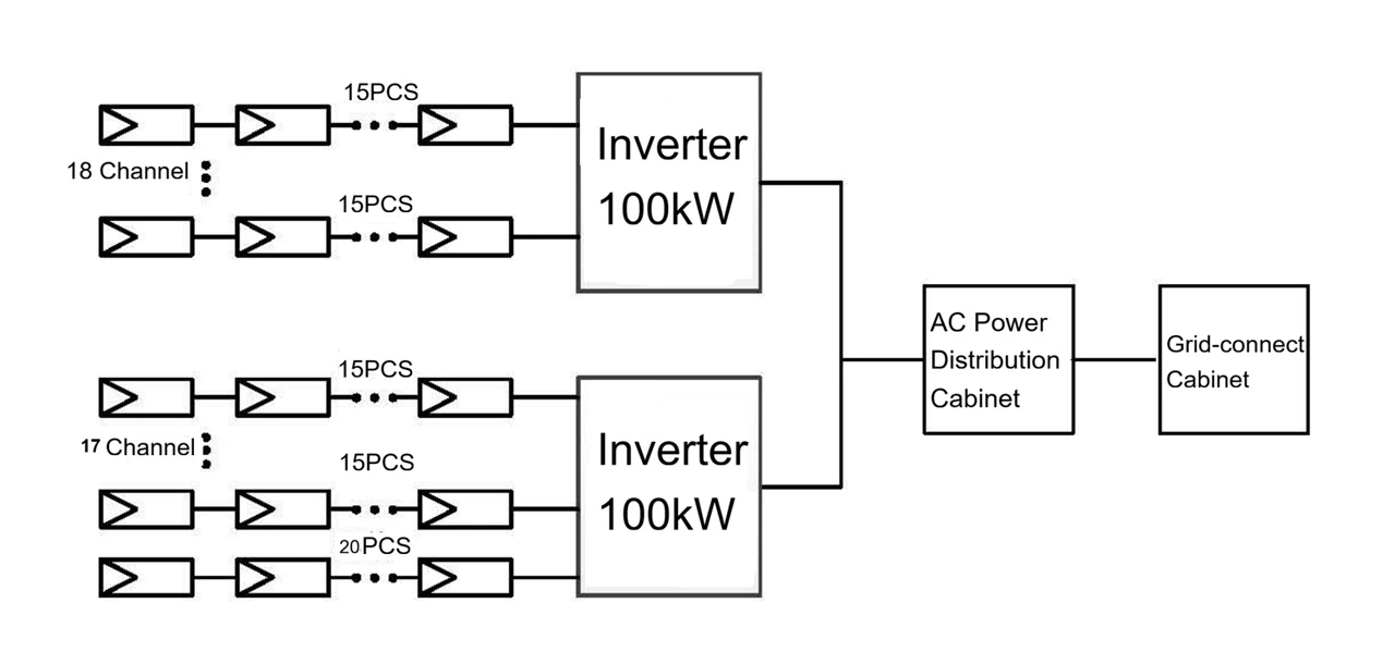
Based on the above data, considering extreme temperatures, the number of PV modules in series is calculated: maximum input voltage 1100V ÷ 49.62V = 22 modules; rated voltage 600V ÷ 49.62V = 12 modules. Therefore, the number of PV modules should be between 12 and 22. To ensure long-term inverter operation, this project selects 15 PV modules per string, connected to the inverter at 750V. If each inverter connects 15 solar panels, there will be a total of 36 input channels, with 35 channels using 15 modules each and 1 channel using 20 modules.
The inverters selected for this project support a maximum of 20 input channels, requiring two 100kW inverters, each connecting 18 module strings. (The capacity ratio is 1.495. Referring to the "NB/T 10394-2020 Photovoltaic Power Generation System Energy Efficiency Specification," a capacity ratio of 1.5 for fixed single-sided modules optimizes the flattened power generation cost, meeting the design requirements.)
Photovoltaic system solution block diagram
5.2 Wind Power System Configuration Scheme
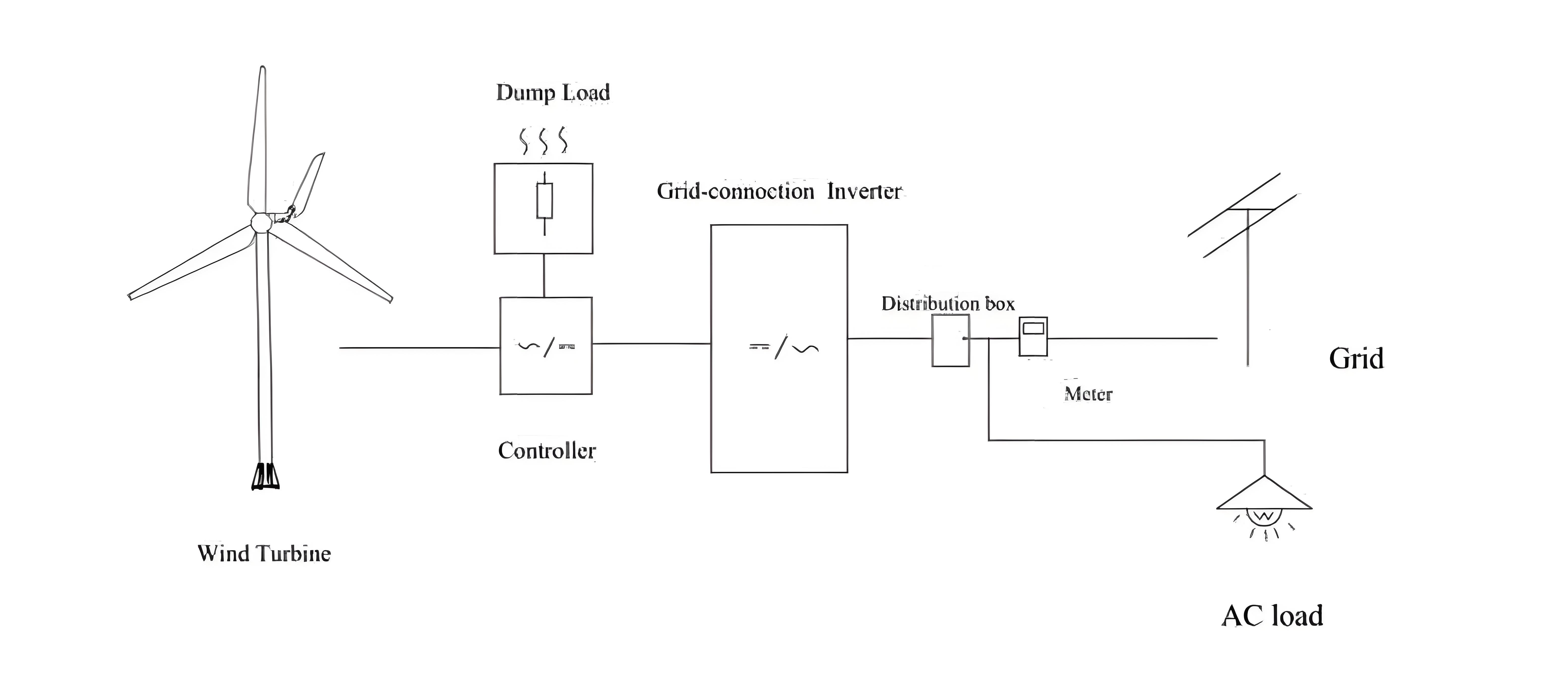
5.2.1 Wind Power Generation System
The wind power grid-connected generation system utilizes wind turbine generators to convert wind energy into AC power. The AC power output from the wind turbine generators, which has unstable amplitude and frequency, is rectified into DC power by a controller and then output to an inverter. The inverter converts the DC power into stable AC power, which, after being metered, is directly fed into the DC power inverter to become AC 380V, 50Hz three-phase AC power.
The AC power output from the grid-connected inverter is fed into a low-voltage AC switchgear and connected in parallel with the AC 380V terminal in the substation. The system uses a 220/380VAC three-phase five-wire output and operates directly in grid-connected to the secondary side of the transformer in the distribution room. The wind power grid-connected generation system has reverse power protection, anti-islanding, short-circuit overcurrent, and overvoltage protection functions to ensure the safe and reliable grid-connected operation of the wind power system.
5.3 Charging System Configuration Scheme
5.3.1 System Scheme
The charging system mainly consists of charging equipment and a monitoring platform. The charging equipment includes five 7kW AC charging piles, one 80kW DC charging pile, and one 120kW DC charging pile. Each selected charging pile consists of a shunt, contactor, charging connection cable and vehicle plug, charging controller, status indicator lights, metering module, and auxiliary power module.
The charging pile can display relevant information for each status, including operating status, charging capacity, and billing information. The displayed characters should be clear, complete, and undamaged, and legible without ambient light. It should have the function and interface for external manual parameter setting and manual control; an internal energy meter should be installed to measure the output energy of the charging pile, enabling remote transmission of charging metering information to the electric vehicle payment cloud platform; and an APP-based QR code scanning function for start/stop functionality should be supported.
5.3.2 Charging piles
Charging Pile Parameter
| 7kW AC Charge Pile | |
| Rated power | 7kW |
| Input voltage | AC220V±15% |
| Input mode: | Single-phase three-wire system |
| Operating frequency | 45~55Hz |
| Output voltage | AC220V |
| Output current | 0~32A |
| Protection rating | IP65 |
| 120kW DC Charge Pile | |
| Maximum output power | 120kW |
| Output voltage range | 200-700VDC |
| Maximum output current | 250A |
| BMS auxiliary power supply | 12VDC |
| Maximum efficiency | ≥95% |
| Rated input voltage | 380AC (three-phase five-wire system, 3W+N+PE); |
| Input voltage range | 304~456Vac |
| Input frequency range | 45~65Hz |
5.4 Energy Storage System Configuration Scheme
5.4.1 System Scheme
The energy storage system is an important part of the microgrid system. It mainly consists of solar batteries, battery management system (BMS), a fire protection system, power conversation system, combiner cabinets, distribution cabinets, and related electrical accessories. Lithium iron phosphate batteries have high safety; they will not explode or burn due to overcharging, over-discharging, overheating, short circuits, or impacts. Furthermore, lithium iron phosphate batteries are environmentally friendly, containing no heavy metals or rare metals, and are non-toxic (CE certified) and pollution-free. Based on the requirements of the photovoltaic system and the load system, this project selects a 100kW/215kWh energy storage system for configuration.Here we choose the Brovolt 100kW/215kWh all-in-one system.
| Brand | Brovolt |
| Cell type | LiFePO4 |
| Configuration | 1P240S |
| Energy | 215kWh |
| Battery voltage range | 672V-864V |
| Grid type | 3P4W |
| Nominal power | 100kW |
| Nominal voltage | AC400V |
| Frequency | 50Hz/60Hz |
| Nominal current | 72A |
| Power Factor | 0.8(Leading)~0.8(Lagging) |
| Output Harmonics | ≤3% |
5.4.4 Energy Storage System Installation Scheme
Regarding the installation of the energy storage system, considering the current site conditions, this project considers two installation schemes: one is to install it using standard containers, placing the containers separately on an open area; the other is to install it in an existing power distribution room, configuring air conditioning, fire protection, lighting, and other facilities as required.
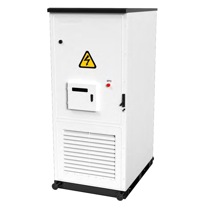
5.4.5.1 Outdoor All-in-one System Cabinet Installation Scheme
This system adopts a standardized system scheme. The general appearance of the outdoor cabinet is shown in the figure below.
When selecting an installation site, please at least follow the following principles:
The climate and geological conditions (such as stress wave emission and groundwater level) of the energy storage integrated system installation site should be fully considered.
· The surrounding environment should be dry, well-ventilated, and far away from flammable and explosive areas.
· The soil at the installation site needs to have a certain degree of compaction. It is recommended that the relative compaction of the soil at the installation site be ≥98%. If the soil is loose, measures must be taken to ensure a stable foundation.
Note: (1) A drainage system should be installed at the installation site to prevent the bottom or internal equipment of the battery or AC outdoor cabinet from being submerged in water during rainy seasons or heavy rainfall.
(2) Do not plant trees within close proximity to the installation site. This is to prevent strong winds from blowing down branches or leaves that could block the doors or air inlets of the battery or AC outdoor cabinet.
Electrical connections must strictly comply with the manufacturer's user manual.
5.5 Photovoltaic Storage and Charging Monitoring System
5.5.1 System Solution
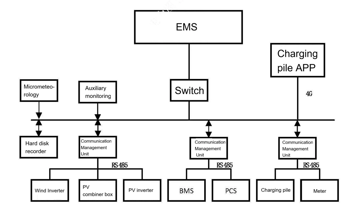
The Photovoltaic-Storage-Charging Microgrid Energy Monitoring System (EMS) provides centralized monitoring and management of equipment such as photovoltaic combiner boxes, photovoltaic grid-connected inverters, wind turbine grid-connected inverters, BMS, and PCS within the microgrid system, as well as related environmental and alarm sensors. The EMS collects equipment information and sensor status data through intelligent data acquisition and transmission modules. Simultaneously, the EMS software also provides equipment alarm functions, enabling customers to promptly handle related faults.
Main functions of the Photovoltaic-Storage-Charging Microgrid Energy Monitoring System include:
1) Monitoring the overall operation status and data of the microgrid.
2) Monitoring the operation data and status of photovoltaic equipment, wind power equipment, energy storage equipment, and charging piles.
3) Displaying current energy flow information of the energy system.
4) Energy management and coordinated control of photovoltaic and energy storage systems.
5) Statistical analysis of electricity consumption, renewable energy usage, and energy-saving data.
6) User management and access control.
7) Important alarm management, etc. 5.5.2 Monitoring and Management
(1) Photovoltaic Monitoring
For photovoltaic power generation systems, the photovoltaic-storage-charging system has the function of online monitoring of photovoltaic panel arrays, environmental monitoring, combiner boxes, and inverters, ensuring the safe operation of photovoltaic power generation.
Measurement Monitoring: Environmental information such as sunshine, temperature, and wind speed; panel temperature, DC voltage, DC current, DC power, and inverter power, etc.
Status Monitoring: AC/DC overvoltage/undervoltage, AC/DC overcurrent, frequency over/under alarms; overtemperature, overload, and leakage protection, etc.
Energy Monitoring: Real-time photovoltaic power generation, total power generation, etc.
Remote Control: Inverter start-up, stop-up, and power adjustment.
(2) Wind Turbine Monitoring
For wind power generation systems, the station-level system has the function of online monitoring of grid-connected inverters, etc., ensuring the safe operation of wind power generation.
Measurement Monitoring: Environmental information such as temperature and wind speed; DC voltage, DC current, DC power, and inverter power, etc. Status monitoring: AC/DC overvoltage/undervoltage, AC/DC overcurrent, frequency over/undervoltage alarms, overtemperature, overload, leakage protection, etc.
Power monitoring: Real-time wind turbine power generation, total power generation, etc.
Remote Control: Inverter start, stop, and power adjustment.
(3) Energy Storage Monitoring For the configured energy storage system, the photovoltaic-energy storage-charging system has the function of online monitoring of solar batteries and PCS bidirectional inverter, ensuring that its remaining capacity is within a reasonable range and guaranteeing the safe and reasonable utilization of the battery.
Measurement Monitoring: Operating mode, power control mode, preset value information such as power, voltage, current, and frequency, lithium ion solar battery charging and discharging voltage, current, SOC, and temperature.
Status Alarm Data: battery storage charging and discharging status, AC/DC overvoltage/undervoltage, AC/DC overcurrent, frequency over/under alarm, overtemperature, overload, leakage protection, etc.
Energy Data: Battery SOC.
Setting Data: PCS start, stop, and power adjustment.
(4) Charging Monitoring The photovoltaic-energy storage-charging system must have the function of providing various measurement monitoring, status monitoring, and energy monitoring for the charging pile.
Measurement Monitoring: Charging current, charging voltage, charging power, charging time, etc.
Status Monitoring: Charging pile status, connection confirmation switch status. Power Monitoring: Real-time charging amount and meter readings during the charging process.
(5) Power Distribution Monitoring: PV-storage-charging system monitors various measurement data, status alarm data, and power data of the high and low voltage side switches of the incoming distribution transformer.
Measurement Monitoring: Current, voltage, power, and frequency of the high and low voltage sides of the distribution transformer.
Status Monitoring: Status of the high and low voltage side switches of the distribution transformer and operation signals of protection devices.
Power Monitoring: Power consumption of the high and low voltage sides of the distribution transformer.
(6) Auxiliary Monitoring: The photovoltaic-storage-charging system monitors the distribution room environment, security, fire protection, and video functions. It can also execute relevant linkage controls based on monitored anomalies to ensure the safety of the operating environment.
5.5.3 Main Functions: The photovoltaic-storage-charging system is the top-level management system of the microgrid, allocating energy in the microgrid according to optimal principles and coordinating the power flow between various power generation units within the microgrid. It can perform functions such as equipment monitoring, photovoltaic monitoring, wind power monitoring, energy storage monitoring, power distribution monitoring, auxiliary monitoring system management, energy statistical analysis, energy management, energy storage dispatching, event alarms, and report management. Related function descriptions:
Equipment monitoring is a module for viewing real-time data from equipment within the system. It allows viewing of real-time data in configured or list-based formats, and enables control and dynamic configuration of equipment through this interface.
The environmental monitoring interface displays ambient temperature and humidity data visually in graphical form.
By statistically analyzing energy consumption data, the system determines the building's energy consumption status and equipment energy efficiency, thereby providing energy management optimization measures. While processing and uploading data, the system categorizes and collects and reports electricity consumption for lighting, air conditioning and heating, office use, elevators, specialized equipment, and other purposes.
The system should support multiple alarm levels (general alarms, important alarms, and emergency alarms). Various alarm threshold parameters and parameters should be configurable. The color, sound alarm frequency, and volume of alarm indicator lights at each level should automatically adjust according to the alarm level. When an alarm occurs, it should automatically alert the user, display alarm information, and provide alarm information printing functionality.
The system also provides functions for querying, statistically analyzing, organizing, and printing equipment data statistics, as well as managing basic reporting software. The monitoring and management system has the function of storing various historical monitoring data, alarm data, and operation records (hereinafter referred to as performance data) in the system database or external storage.
The energy management system completes the collection and data monitoring of battery BMS information in the system, intelligent control of equipment such as energy storage converters, and realizes functions such as energy storage system charge and discharge management, grid-connected/off-grid switching, and optimized control.
The auxiliary monitoring system refers to the centralized monitoring of variables such as the substation environment, security, fire protection, and video. Power supply, air conditioning and other power equipment, as well as the substation environment, are the foundation for ensuring the safe and stable operation of the system. For intelligent air conditioning and intelligent lighting management, the RS485 interface can collect environmental temperature and humidity, remotely start/stop, set temperature, set operating mode, and other operations, thereby realizing remote monitoring and control of air conditioning and minimizing energy consumption.
5.5.4 Energy Management Based on the operating parameters, constraints, and predicted data of each system, energy coordination and control strategies are formulated to realize the interaction, integration, and flexible allocation of energy among the distribution network, distributed renewable energy generation, charging facilities, and energy storage devices.
Connecting photovoltaic and wind turbines can not only improve this problem, but also help with energy conservation and emission reduction. Meanwhile, energy storage has the characteristics of flexibility, dispatchability and rapid response. Electric vehicles are also a demand-side dispatchable resource. Therefore, by using the joint dispatch of photovoltaic, wind turbine, energy storage and electric vehicle loads, on the one hand, the time distribution characteristics of charging load can be improved, so as to achieve the goal of prioritizing the absorption of photovoltaic and wind turbine power and reducing the impact on the power grid; on the other hand, it can reduce users' charging costs and increase revenue, thus achieving a win-win situation in terms of economy.
The energy management control strategies involved in this project are as follows:
(1) Grid-connected automatic operation strategy
1. The power generation equipment is kept in the activated state. During grid-connected operation, the microgrid is allowed to feed power back to the mains, so it is necessary to ensure that the power generation equipment is in the activated state to maximize the utilization of clean energy.
2. If the solar battery's SOC value is below 90%, charging begins, and charging stops when the SOC value reaches 100%.
3. During discharge, if lithium ion solar battery's SOC value is below 15%, the system alarms once, but does not stop discharging. When the SOC reaches 5%, discharging stops, and an alarm is triggered.
4. The power adjustment for charging and discharging is in 5kW increments, with only 5kW being adjusted each time.
5. The strategy only adjusts the charging and discharging when the difference between the power generation of the power generation equipment and the power consumption of the load exceeds 5kW.
(2) Peak Shaving and Valley Filling Strategy
1. Based on time-of-use pricing information, define charging and discharging time periods, and set various charging and discharging modes (one charge and one discharge, two charge and two discharge, etc.);
2. When the power generation of distributed power sources exceeds the load consumption, prioritize using the distributed power source's electricity to charge the battery. Once the battery is fully charged, it can then feed power back to the grid;
(3) Grid-Connected Power Feed Source Monitoring Strategy
1. During peak electricity consumption periods, monitor the power feed from the PCC point, the microgrid's power generation, and its power consumption. After calculation and analysis, allow the self-generated power exceeding the load to feed back to the grid.
2. By detecting the power generation and load consumption of the microgrid's power generation equipment, and combining this with the execution time of the energy storage strategy, the self-generated power of the microgrid system stored in the energy storage system can be calculated. If it is necessary to dispatch the stored power to the main grid during peak electricity consumption periods, the power must not exceed the self-generated power of the microgrid system stored in the energy storage system. (4) Optimize operation strategy. For the optimized scheduling of distributed energy generation, distribution network, energy storage and electricity load, the generation information and load information of distributed power sources can be predicted by combining power generation data, weather data and historical data. An optimization model can be built by combining relevant electricity prices, energy storage charging and discharging power and power. The scheduling strategy of each system of wind, solar, energy storage and charging can be determined by algorithms such as neural network and particle swarm.