This article is extracted from the technical plan of the parking lot photovoltaic storage and charging integrated project.
The project site is located in Ganzhou City, Jiangxi Province, which belongs to the South Asian tropical monsoon climate. The annual average temperature is 20.6℃, the annual average daily solar radiation is 3.48kWh/㎡, and the annual solar radiation is 1270.7kWh/㎡. The solar radiation is very rich, which is suitable for laying photovoltaic systems. When there is sufficient sunlight during the day, if the electricity generated by the photovoltaic system cannot be consumed in time, the energy storage system can store the electricity in time and supply power to the charging piles at night.
This project includes three parts: photovoltaic, energy storage and charging piles, and the project installation point is Ganzhou City. The technical plan was made by Brovolt based on customer needs and field surveys. This article explains the selection ideas and technical parameters of the energy storage system in the photovoltaic storage and charging plan.
1. System solution
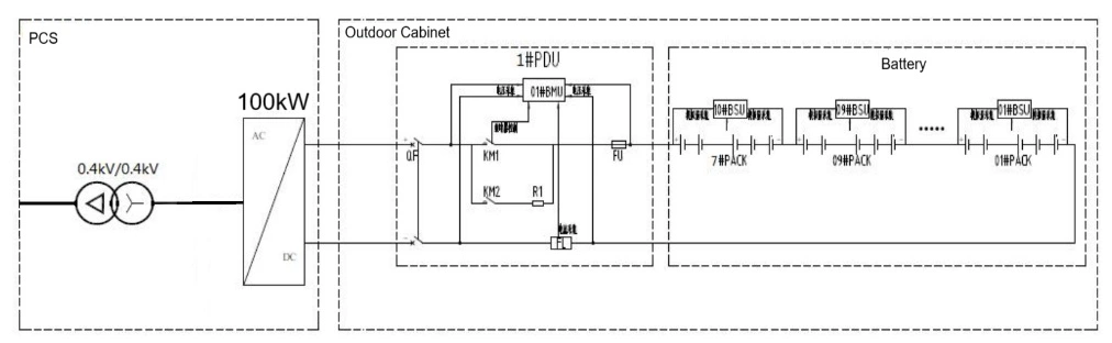
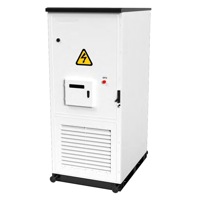
According to the overall project plan configuration, the energy storage system configuration specification is 100kW/240kWh, and it is installed in the form of an outdoor cabinet. The system mainly includes: lithium iron phosphate battery (Pack), battery management system (BMS), high-voltage control box (PDU), air conditioning, distribution box, outdoor cabinet, and PCS.
2. System Composition
2.1 Energy storage Battery System
The energy storage battery system adopts 314Ah/3.2V lithium iron phosphate cells, which consist of one battery cluster. 1P24S forms a 24.115kWh battery box. Ten battery boxes are connected in series to form a 241kWh battery cluster, with a voltage range of 672 to 864V. This system has two battery clusters with a total capacity of 241kWh. Multiple sets of energy storage battery systems can be used in parallel.
| Item | Parameter |
| Cell | LeFePO4 /314Ah |
Configuration | 1P240S |
Nominal Voltage | 768V |
Voltage range | 672~864V |
Nominal Energy | 241kWh |
Nominal power | 100kW |
Temperature | -30~55℃ |
Relative humidity | 0~95%(No condensation) |
Altitude | ≤2000m |
Protection class | IP54 |
Dimension | 1500*2100*1330mm |
Communication | RS485,CAN,RJ45 |
Cooling method | Air force cooling |
3) High-voltage control box:
The high-voltage control box (PDU) is composed of fuses, circuit breakers, contactors, shunt devices, BMS main control units, etc. The main functions of each component are as follows:
Fuse (FU) : It serves to protect against overload or short circuit in the circuit.
Circuit Breaker (QF) : The main output switch of the battery system, which cuts off the circuit when abnormal operating conditions occur in the system.
Shunt (FL) : For BMS current detection and information collection;
Contactor (KM) : Controls the charging and discharging circuits;
BMS master control: As the control center, it is responsible for the monitoring of the entire system's operation process, data processing, implementation of control strategies, and communication control
2 Battery Management System (BMS)
The battery management system adopts a three-level architecture and is equipped with a total of 10 24-string slave controllers (BSU) and 1 master controller (BMU).One BMS heap controller (BDU), supporting active equalization.
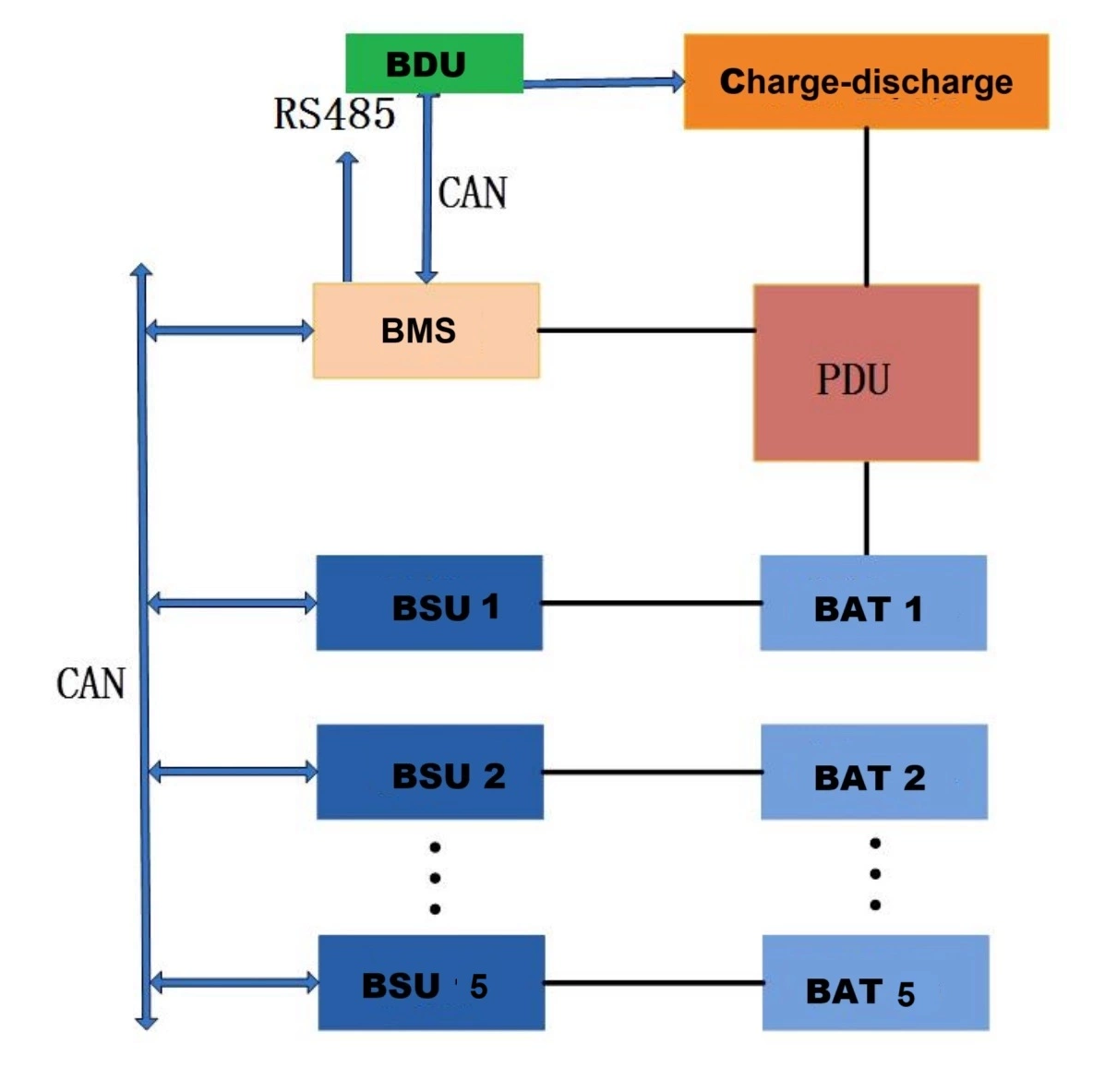
1) BDU module parameters and main functions
The BDU is at the top of the three-tier architecture of the battery management system and is mainly responsible for collecting real-time data of the BMU.It integrates real-time computing, performance analysis, alarm handling, protection handling and record storage. In addition, BDU is also responsible for storage.The power conversation system (PCS) and the upper-level energy management system (EMS) communicate to achieve interconnection
| Item | |
| Liquid crystal screen | 7"TFT true-color LCD screen (16:9 aspect ratio), resolution 1024×600 |
| CPU | NXP/Freescalei.MX7Dual |
| Memory | 1GBytesDDR3SDRAM |
| Storage device | EMMC8G |
| Expanded storage | SD card storage, with a maximum support for expansion up to 32G |
| Power input | Wide voltage input of DC9V to 24V, it is recommended to use DC12V or 24V input |
BDU main functions:
a) Local operation status display function: Through the UI interface of BDU, various operation statuses of the battery system can be displayed locally, such as system status, individual battery voltage, temperature, SOC, SOH, alarm and protection information.
b) Communication protocol conversion function: Supports Modbus-TCP protocol conversion and conducts information interaction with the energy management system through the Modbus-TCP protocol.
c) It has the function of communicating with PCS: It supports information interaction with PCS through the CAN interface to achieve the charging and discharging control of the battery stack.
d) Operation parameter setting function: The various parameters of the battery management system operation can be modified, configured and saved through BDU.
(2) BMU module parameters and main functions
The BMU is a controller module integrating functions such as cluster total voltage/total current collection, charge and discharge management, insulation detection, and BSU management. Its characteristic parameters are as follows:
| Item | Specification |
| Module working power supply | 15V~32V |
| Total voltage sampling range | 0-1500Vdc |
| Total voltage sampling accuracy | ±0.5% |
| Total current collection range | Determined by the shunt and the Hall current sensor |
Total current collection accuracy | ±1%FS |
| Temperature collection range | -20℃-105℃ |
| Temperature acquisition accuracy | ±2℃ |
| Insulation resistance collection range | 0-10M |
| Insulation resistance collection accuracy | 50kΩ以下±10kΩ , 50kΩ以上±20% |
BMU Main features:
a) The current acquisition sensor is compatible with multiple models such as shunt sensors, LEM Hall sensors, open-loop Hall sensors, and closed-loop Hall sensors.
b) The battery management system should be capable of detecting data related to battery heat and electricity, at least including parameters such as insulation resistance and internal and ambient temperatures.
c) The battery management system should be capable of estimating the state of charge (SOC) and battery health (SOH) of the battery, and conducting automatic calibration. It is capable of calculating, real-time local display and reporting the number of cycles (calculation formula: cumulative charge/(nominal capacity *90%), DOD, SOC, SOH). The battery can automatically perform SOC calibration and battery balancing during operation.
d) The battery management system plans the charging and discharging control of the battery based on its state of charge. If the battery voltage exceeds the standard or there is an overcurrent, the system must immediately stop the battery operation.
e) Battery system operation alarm function: When the battery system operates in states such as overvoltage, undervoltage, overcurrent, high temperature, low temperature, abnormal communication, or abnormal battery management system, it should be able to display and report alarm information.
f) The battery management system should have the function of information interaction with the converter, local monitoring device and energy management control system, and should provide RS485, CAN and Ethernet communication interfaces.
3) BSU module parameters and main functions
The BSU provides real-time collection of individual cell voltage and temperature, and also features thermal management and bidirectional active balancing capabilities. It is interconnected with the main control module via the CAN bus.
| Item | Specification | Remark |
| Module working power supply | 15V~32V | |
| Number of battery detection strings | 24S | |
| Temperature detection points | 12 | |
| Single-cell voltage monitoring range | 0~4.5V | Error ±2mV |
| Temperature collection range | -40℃~120℃ | Error ±1℃ |
| Battery balancing principle | Bidirectional active equilibrium + passive equilibrium | |
| Balanced current (constant current) | Maximum 2A, with automatic current regulation | |
The main functions of BSU:
a) It supports parameter configuration function. Parameters can be configured based on the actual number of battery strings connected and the number of temperature sensors. It also allows for the configuration of heating/fan on/off temperatures.
b) Configurable active balancing or passive balancing is available. The battery management system should have a balancing management function, capable of balancing the inconsistent differences among battery packs and clusters.
c) The battery management system should be capable of detecting thermal and electrical data related to the battery, at least including parameters such as the voltage, current, insulation resistance, and internal and ambient temperatures of individual battery cells and battery packs.
d) The battery management system should be capable of diagnosing battery faults, providing disconnection protection, balancing fault detection, and handling corresponding faults based on specific fault contents. It should have, but not be limited to, the following protection functions: overcharge protection, overdischarge protection, short-circuit protection, overload protection, and temperature protection. The relevant fault information should have functions such as fault information upload and real-time alarm.
2.3 Distribution Box
The incoming line of the secondary power distribution system is single-phase three-wire, which can provide independent control switches and 220V single-phase AC power supply for AC power equipment such as outdoor cabinet air conditioners, switching power supplies, fire protection, and sockets, to ensure the stability of the system. The 220V power supply is provided externally.
2.4 Air Conditioning System
The system is equipped with an industrial air conditioning system to regulate the temperature inside the outdoor cabinet. When the battery temperature is detected to reach a certain limit value, an instruction is sent to the air conditioning system to control it to start operating, keeping the system temperature inside the box within an appropriate range. The system has four working modes.
Refrigeration
The parameters of the air conditioner can be set through the display screen or the background software: the set cooling temperature and the cooling deviation temperature. When the temperature inside the chassis is higher than (the set temperature for refrigeration + the deviation temperature for refrigeration), refrigeration begins. When the temperature inside the chassis is lower than the set temperature for cooling, the cooling will stop.
(2) Heating
The air conditioner can be set with parameters: heating set temperature and heating deviation temperature. When the temperature inside the chassis is lower than the set heating temperature, heating begins. When the temperature inside the chassis is higher than (the heating start temperature + the heating deviation temperature), the heating stops.
(3) Supply air
The air conditioner can achieve uniform temperature distribution inside the chassis through the air supply function, avoiding local overheating inside the box. When the temperature inside the unit is lower than the cooling start temperature, the air supply function will be automatically activated.
(4) Dehumidification
When the humidity inside the box is greater than the humidity at which the dehumidification is activated and the temperature inside the box is lower than the temperature at which the dehumidification is activated, the electric heating dehumidification is connected. Stop heating when the temperature inside the box rises to the dehumidification stop temperature or the humidity drops back to the dehumidification stop humidity.
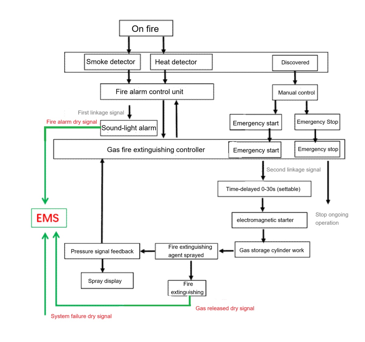
2.5 Fire Protection System
The fire protection system equipped in this energy storage battery system has two control modes: automatic and manual. When the alarm controller is in the automatic state and receives the first linkage signal, the sound and light alarm will sound an alarm, indicating the location where the fire occurs and reminding the staff to pay attention. When the second linkage trigger signal is received, the automatic fire extinguishing controller begins to enter the delay stage (adjustable from 0 to 30 seconds), and the delay is too long
Afterwards, the controller issues a fire extinguishing command, opens the solenoid valve, then opens the gas storage cylinder to carry out fire extinguishing operations in the fire area. At the same time, the alarm controller receives the feedback signal from the pressure signal device, and the spray indicator light on the control panel lights up. When the alarm controller is in manual mode, it only issues an alarm signal and does not output an action signal. After the on-duty personnel confirm the fire alarm, they can press the emergency start button on the alarm control panel or the emergency start-stop button at the entrance of the protected area to start the system and release the fire extinguishing agent.
3.Power conversation system(PCS)
The energy storage system is equipped with 100kW power conversation system, featuring a modular architecture and supporting both on-off and off-grid modes.
3.1 Parameters
| Nominal power | 100kW |
| Grid type | 3P4W |
| Nominal voltage | 400V |
| Max power | 110kW |
| Frquency | 50/60Hz |
| THDi | ≤3% |
| Power factor | 0.8(leading)~0.8 (lagging) |
| Maximum conversion efficiency | 95.5% |
| Weight | 40kg |
| Noise | <75db |
| Protection class | IP20 |
| Cooling method | Air cooling |
| Relative humidity | 0~95% (no condensation) |
| Altitude | <3000m |
| Communciation | Modbus TCP/RTU ,IEC104 |