This atlas is a schematic diagram for the installation of solar panels, and it includes the following parts:
Schematic diagram of PV roof layout
Show the layout of solar panel on sloping roofs or color steel tile roofs, including key parameters such as arrangement direction, module spacing, and installation Angle.
Schematic diagram of PV flat roof
Show the layout form of solar panel on a concrete flat roof, including the arrangement of brackets, the setting of passageways, the maintenance distance and the design of inclination angles, etc.
Schematic diagram of the installation of embedded bolts for PV flat roof supports
Show the pre-embedding method of the foundation bolts of the PV support on the concrete roof, including bolt positioning, pre-embedding depth, fixation method and waterproofing treatment requirements.
1.Schematic diagrams of photovoltaic roof layout
Schematic diagrams of PV flat roof layout, PV pitched roof layout, and photovoltaic curved roof layout. They show the installation methods of solar panels on different types of roofs.
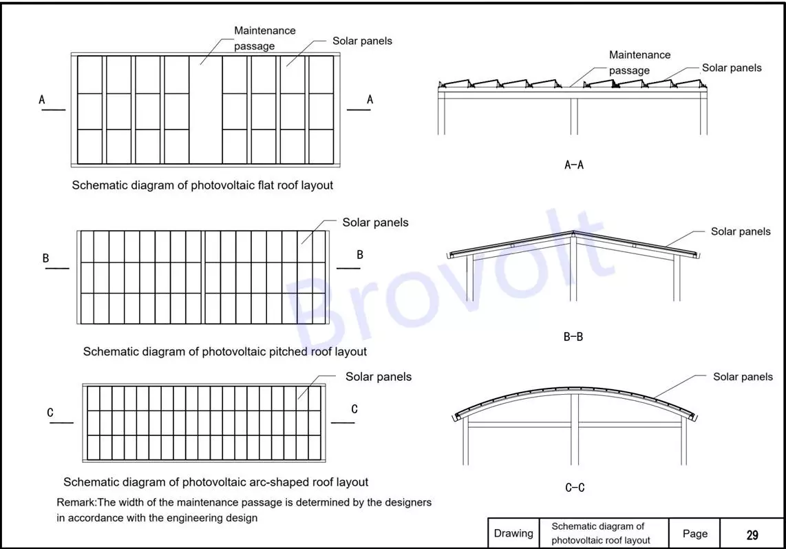
Figure 1.Schematic diagrams of PV roof layout
2.Note: 1. In the figure, D1, D2 and D3 are determined based on the analysis and calculation of sunlight exposure. It is necessary to avoid shading the solar panels.
2 .The installation inclination Angle α shall be confirmed by the designer based on the optimal inclination Angle of the project location and other load effects
3. In order to receive more solar radiation. For a PV array slope, the different incident angles of the sun on it will result in different amounts of normal solar radiation received per unit area. The larger the incident Angle (the Angle between it and the normal perpendicular to the PV array), the less normal solar radiation received (for the same radiation input). The change in the inclination Angle of the PV array will cause the incident Angle of the sun to change, thereby affecting its radiation reception. Therefore, it is necessary to obtain an optimal inclination Angle based on the annual radiation reception through theoretical calculation, and this inclination Angle is the best inclination Angle.

Figure 2 .Schematic diagrams of PV roof layout
3.Sealant: Seal tightly to ensure waterproof sealing performance.
Solar brackets: Selected according to design requirements, it must be firmly connected to the roof structure.
Steel beam: load-bearing structure, connecting embedded parts and supports.
Embedded steel plates/embedded parts: Used for fixing the support system and anchoring with the structural layer.
Thermal insulation and heat prevention board: Maintain the roof's heat insulation performance and prevent thermal bridge phenomena.
Installation Instructions:
The specific construction method of the roof should be determined by the designers based on the actual engineering conditions.
The dimensions and specifications of solar panel must be determined through load calculation.
When installing the PV system, the height requirements from the lowest point of the components to the completed roof surface are as follows:
Common installation method: ≥300mm;
Special structure: ≥200mm;
Slope overhead installation: ≥100mm.
This diagram is a schematic diagram of the root fixation method

Figure 3 PV flat roof supports embedded bolts &members
4.Stone concrete: Used for roof leveling and reinforcement to ensure the firmness of the support foundation.
Solar brackets: It is used for installing and fixing solar panels. The selection should be based on the load and structural requirements.
Sealant: Used for sealing interfaces and penetration points to prevent rainwater leakage.
Embedded bolts: They are pre-embedded in the structure to anchor the support system and ensure a reliable connection.
Installation Instructions:The specific construction method of the roof should be determined by the designers based on the actual situation of the project.
The dimensions and specifications of the connecting components of solar panels should be determined based on load calculation.
When installing solar panels, the distance between their lowest point and the completed roof surface should meet the following requirements:
General installation method: ≥300mm;
Special structural conditions: ≥200mm;
Overhead installation along the slope: ≥100mm
This diagram is of the root installation method
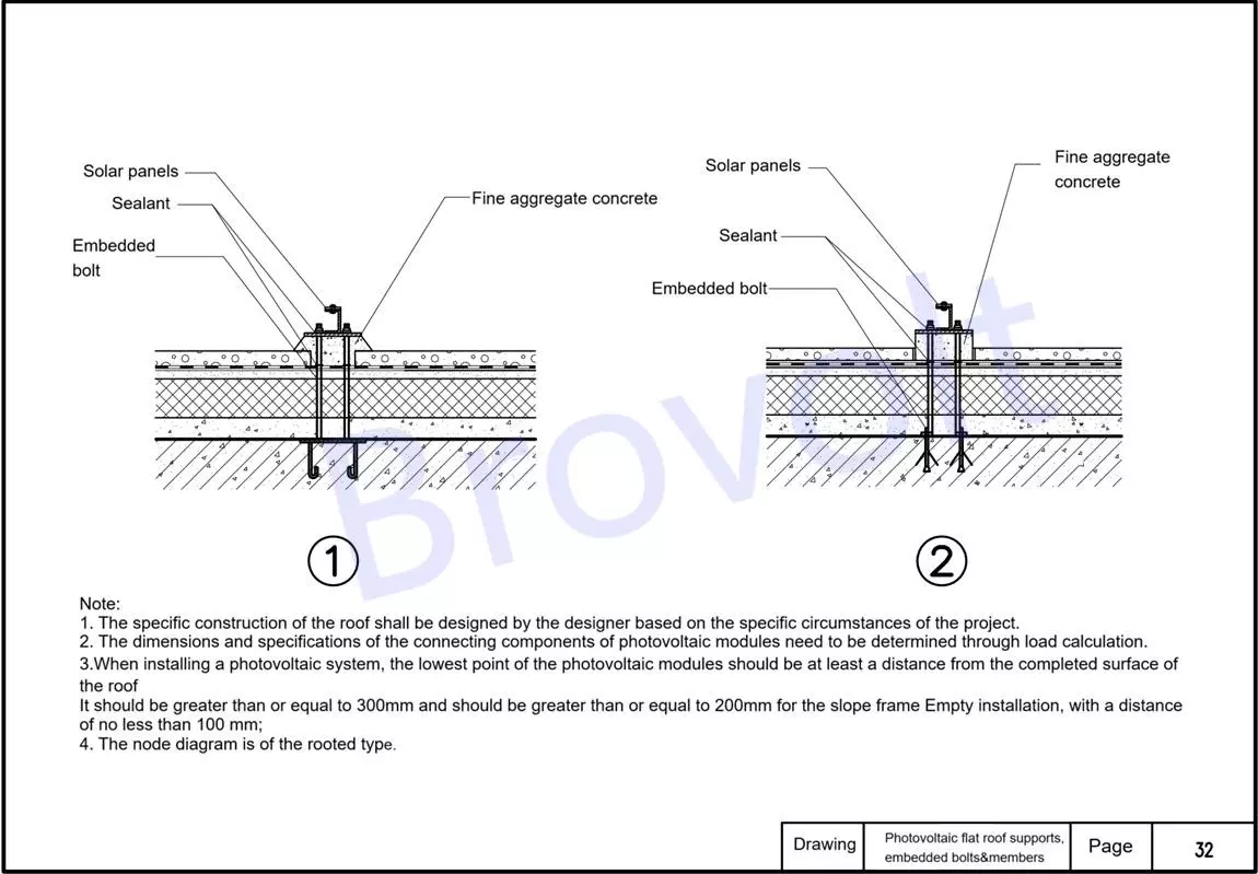
Figure 4. PV flat roof supports embedded bolts &members
5.Anchor bolts: They are used to fix the connection between the PV support and the structural foundation, ensuring the stability of the support.
Solar brackets: It is used to support and fix solar brackets, and is selected based on the design load.
Sealant (sealing treatment) : It is used for sealing all penetration points and joint areas to ensure the waterproof performance of the system.
Concrete structure layer: The load-bearing part of the roof, providing basic support for the brackets.
Embedded bolts: Pre-installed in the concrete and connected to the support to form an anchoring system.
Isolation layer: Prevents reactions or damage between different materials, and is usually made of flexible materials.
Waterproof layer: A key waterproof protective layer for the roof to prevent rainwater from seeping into the interior of the structure.
Installation Instructions:
The roof structure and construction methods should be determined by the designers according to the specific circumstances of the project.
The dimensions and specifications of the solar bracket connectors should be confirmed based on the load calculation.
When installing solar panels, the lowest point and the completed surface of the roof should meet the following requirements:
Standard installation: ≥300mm;Special scenarios: ≥200mm;Overhead installation along the slope: ≥100mm
This picture shows the installation method of the root-planted solar bracket.
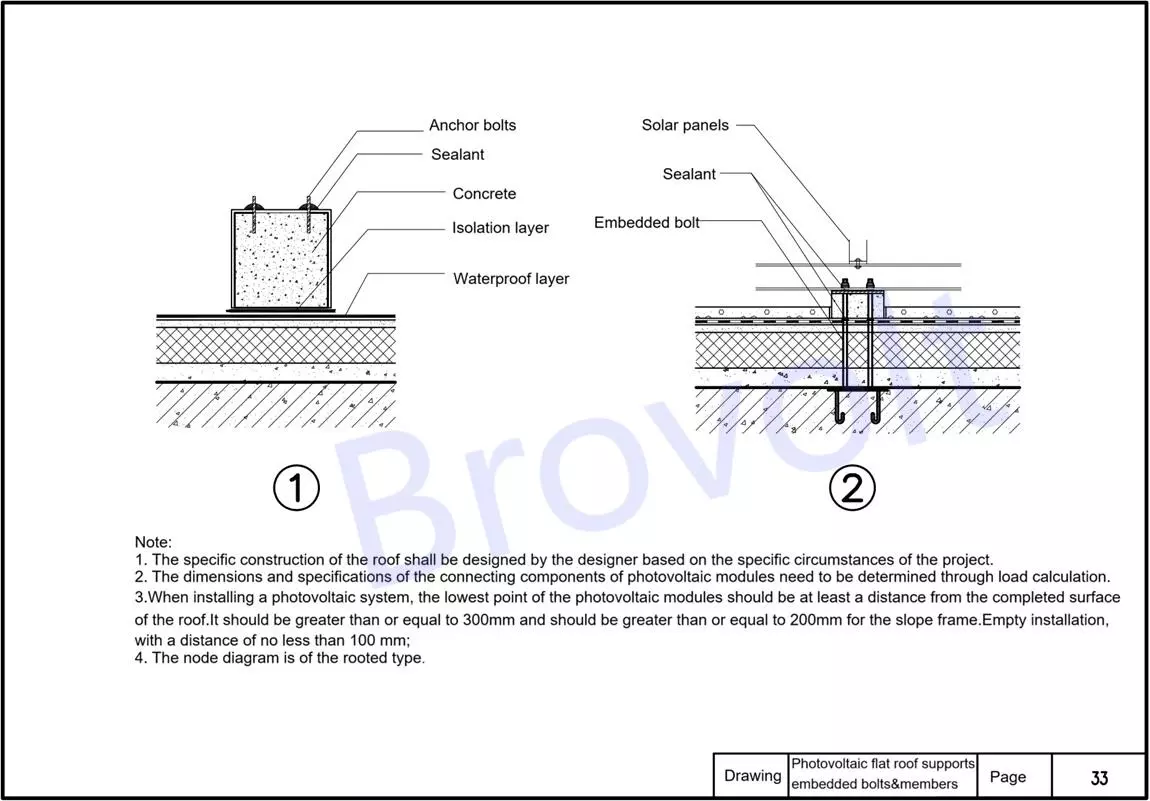
Figure 5. PV flat roof supports embedded bolts &members
6.PV foundation fixed embedded parts: Embedded in the reinforced concrete roof panels, they serve as the anchoring foundation for the support system. The burial depth requirement should be determined based on the specific engineering structure load and construction drawings.
Waterproof fine aggregate concrete layer: It serves to protect and prevent water, and also covers the embedded parts. The thickness is determined by the design.
Waterproof, thermal insulation and slope finding layer (2% slope finding) : It realizes the roof drainage function and also has thermal insulation effect. The slope is 2%, which is conducive to drainage.
Waterproof membrane layer: It provides the main waterproof protection and should be tightly overlapped with qualified detailed treatment.
Waterproof mortar layer: Located beneath the membrane, it serves as a leveling and protective layer, enhancing adhesion and waterproof performance.
Main installation instructions:
The dimensions and specifications of the connecting components of solar panels must be determined based on load calculation.
When installing a PV system, the lowest point of the components should meet the following conditions from the completed surface of the roof:
Ordinary installation ≥ 300mm;Special scenarios ≥ 200mm;Overhead installation along the slope should be ≥ 100mm
The structural heights such as h1, h2, h3, and h4 in the nodes should be determined by the designers based on the actual engineering conditions.
This is an inverted roof structure and is also applicable to the upright roof construction.
The fixed form of the solar bracket is a load-bearing structure, and the embedded parts are anchored here, providing overall structural stability.
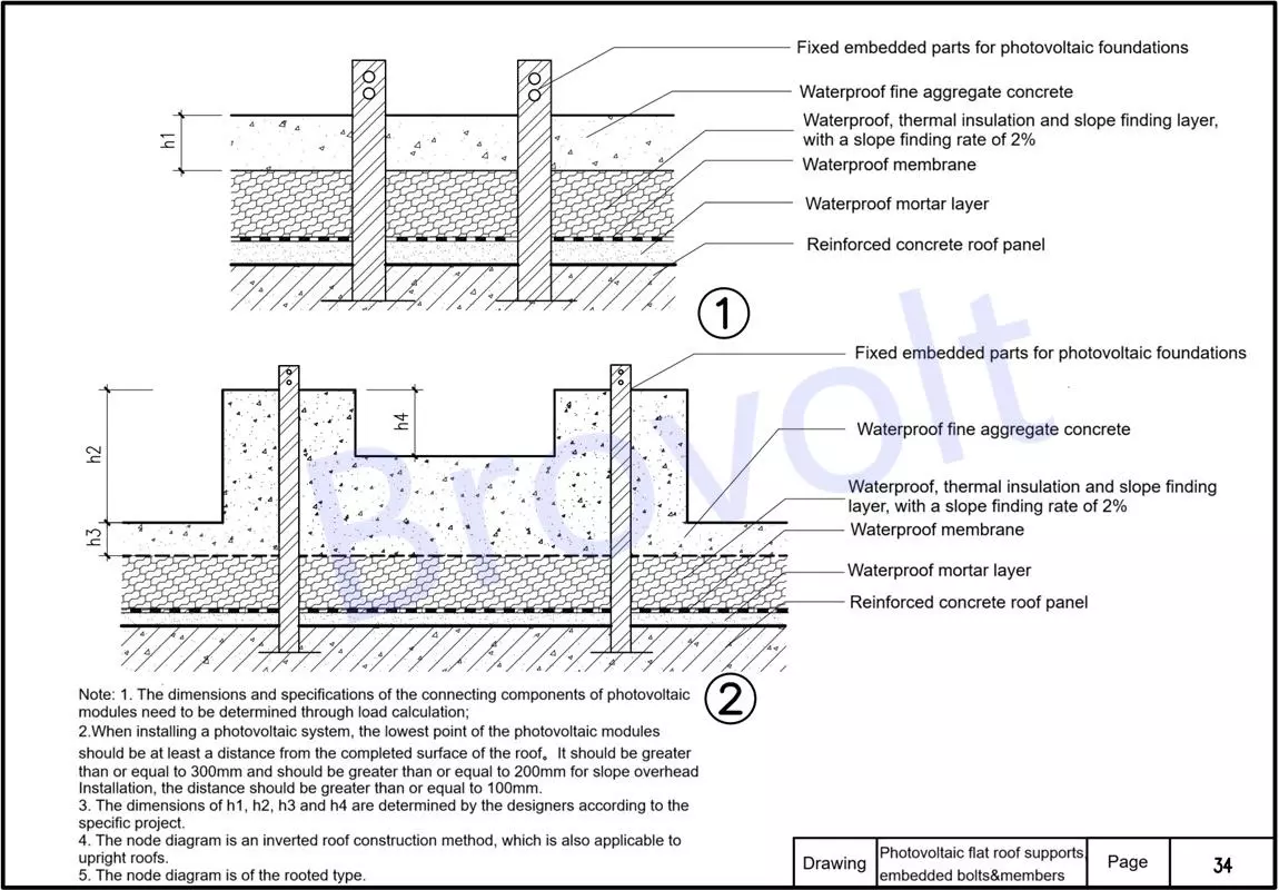
Figure 6. PV flat roof supports embedded bolts &members
7.Metal anchor plates and PV foundation fixed embedded parts: Metal anchor plates are connected to embedded parts through steel mesh sheets to form a stable anchoring system. The embedded parts should be anchored in the reinforced concrete roof panels. The specific burial depth shall be determined by the designers according to the structural requirements of the project.
Waterproof fine aggregate concrete layer: It is used to cover the metal anchor plate area to enhance the waterproof and anti-corrosion effects.
Lightweight cushion layer (waterproof slope finding layer) : It realizes the roof drainage function, with a slope of 2%. At the same time, it plays a transitional and buffering role.
Insulation layer: It ensures the thermal performance of the building and prevents thermal Bridges. Commonly used materials include polystyrene board and rock wool.
Waterproof membrane layer: The main waterproof layer. The overlapping of the membranes should be tight, and the laying sequence should comply with the construction specifications.
Waterproof mortar layer: Leveling the base layer, providing protection, and enhancing the adhesion of the membrane.
Reinforced concrete roof panel: The load-bearing structural layer of a building's roof, supporting the entire upper system.
Installation Instructions:
The dimensions and specifications of the connecting components of solar panels must be selected and confirmed based on the load calculation.
The height from the lowest point of the solar panels to the completed roof surface should meet the following requirements:
General installation: ≥ 300mm;
Special structure: ≥ 200mm;
Slope overhead installation: ≥ 100mm
The height parameters such as h1, h2, h3, h4 and h5 in the figure need to be determined by the designers in combination with the on-site conditions.
This drawing is applicable to inverted roof structures and is also suitable for the construction form of upright roofs.
The root-planted PV foundation installation method is adopted, which features a stable structure and is suitable for permanent layout.
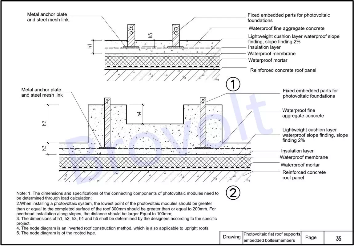
Figure 7 PV flat roof supports embedded bolts &members
8.The metal anchor discs are connected to the roof structure through steel mesh sheets to ensure reliable overall anchoring.
Fixed embedded parts for photovoltaic foundations: The embedded depth should be determined by the designer based on the specific engineering structure and load-bearing requirements.
Waterproof fine aggregate concrete layer: It serves to level the structure, protect the anchor fasteners and provide additional waterproofing.
Base layer (connection transition layer) : A structural layer that combines the old and new roof layers, such as vapor barrier layer, leveling mortar layer, etc.
Existing roof construction methods: Retain the original roof structure, including insulation layers, waterproofing membranes or other functional layers.
Rigid waterproof layer and structural plate tie bars: Set up reinforcing bars to form a firm connection with the structural layer, effectively controlling deformation or displacement caused by increased load.
Reinforced concrete roof panel: The original load-bearing roof structure, serving as the basic carrier for overall anchoring.
Installation requirements description:
The dimensions, quantities and installation methods of the connecting components of solar panels should be professionally designed based on the calculation of structural loads.
Distance requirements from the lowest point of the solar panel to the completed roof surface:
General installation: ≥ 300mm;
Special structural conditions: ≥ 200mm;
Slope overhead installation: ≥ 100mm
The height parameters such as h1, h2, h3, h4, and h5 shown in the figure are determined by the design unit based on the on-site conditions and the building structure.
This diagram is a root-anchored installation, which is suitable for the installation and renovation projects of PV systems on the roofs of existing buildings. Special assessment and treatment of structural safety are required.
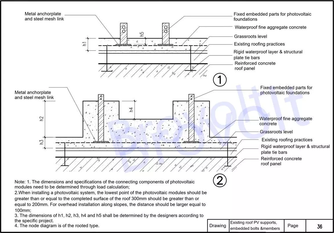
Figure 8.eExisting roof PV supports embedded bolts members