In a smart parking lot energy solution that integrates photovoltaic power generation, energy storage, and EV charging,
the PV system serves as the primary source of clean and renewable electricity. This solution features a 100kWp solar power system designed to efficiently convert solar energy into usable electricity for EV chargers and battery storage. Strategically installed across the parking structure, the PV modules maximize rooftop or canopy space while reducing carbon emissions and operational costs. By generating power during daylight hours, the PV system minimizes grid dependency and enhances energy self-sufficiency. This section provides a detailed overview of the PV system design, component selection, installation methods, and its key role in enabling a sustainable and cost-effective parking lot energy solution.
I. Photovoltaic Solutions
1. Project Overview
1.1. Project Location
The project site is located in Ganzhou .Ganzhou is situated in the upper reaches of the Ganjiang River, in the south of Jiangxi Province, and has a typical subtropical monsoon climate. The geographical coordinates are between 24 °29 'and 27 °09' north latitude and 113 °54 'and 116 °38' east longitude. The annual average temperature is 20.6℃, the annual average daily solar irradiation is 3.48kWh/㎡, and the annual solar irradiation is 1270.7kWh/㎡. The solar irradiation is very abundant. Suitable for laying photovoltaic systems.
This project consists of three parts: photovoltaic, energy storage and charging piles. The installation site is located in Ganzhou. After on-site investigation, there are no tall buildings blocking the installation site around it, and the lighting conditions are good, which is suitable for installing photovoltaic. When there is sufficient sunlight during the day, if the electricity generated by the photovoltaic system cannot be consumed in time, the energy storage system can store the electricity promptly and supply power to the charging piles at night.
1.2. Project ScaFigure 1-1 Floor plan of the parking lotle
The project plans to build photovoltaic carports at parking Spaces. There will be a total of 30 parking Spaces. solar panels will be laid on the photovoltaic carports, and the solar panel is planned to use 545Wp solar panels.
The floor plan of the parking lot is shown in Figure 1-1. The parking lot has two rows of parking Spaces, with a total of 30 parking Spaces. Among them, there are 16 parking Spaces in the first row and 14 in the second row. Photovoltaic carports can be designed and customized according to the customer's requirements for the height, width and appearance of the carport. Figure 1-2 shows the design drawing of a certain type of photovoltaic carport for reference.
According to the site plan of the parking lot, solar panels are laid. No maintenance passages are reserved between the solar panels. The solar panels used are 545Wp solar panels, with each module measuring 2256*1133mm. A total of 180 solar panels can be laid, and the installed capacity is 98.1kW. The specific laying diagram is shown in Figure 1-3.
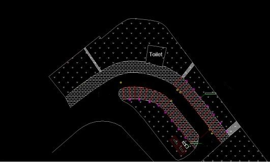
Figure 1-1 Floor plan of the parking lot
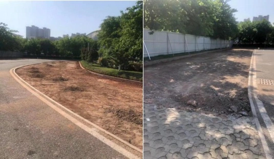
Figure 1-2 Pictures of the project site
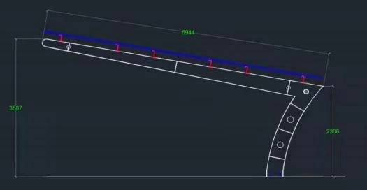
Figure 1-3 Schematic diagram of the photovoltaic carport
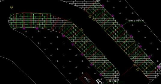
Figure 1-4 Schematic diagram of solar panel laying
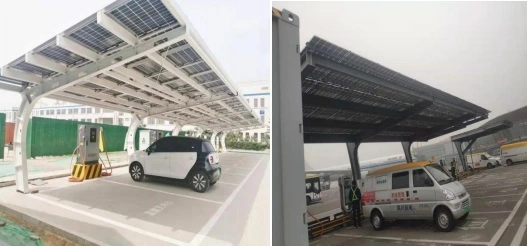
Figure 1-5 Effect diagram of solar panel laying
2. Description of the photovoltaic system solution
2.1 Selection and Design of Photovoltaic Systems
2.1.1 Selection of solar panels
Taking into account the photoelectric conversion efficiency and power density of solar panels comprehensively, a 545Wp monocrystalline single-glass module with a relatively high cost performance is selected. This series of modules have the advantages of high power generation, long service life and good reliability. The attenuation in the first year is
less than 2%, and it decreases by 0.55% each year thereafter.
The output power is guaranteed for 25 years. The external dimensions are shown in Figure 2-1. The detailed technical parameters of this component are shown in Table 2-1 below.
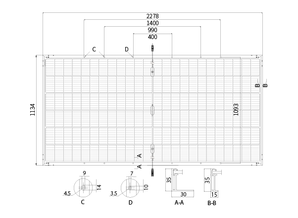
Figure 2-1 Diagram of the external dimensions of solar panel
| PV module type | Single crystal silicon |
| Arrangement of battery cells | 144(6×24) |
| Junction box | IP68, split junction box |
| Output line | 4mm² , +400 ,-200mm |
| Glass | Single glass, 3.2mm tempered glass |
| Weight | 27.2kg |
| Module size | 2278× 1134×35mm |
| Maximum power (Pmax) | 545W |
| Open-circuit voltage (Voc) | 49.65V |
| Short-circuit current (Isc) | 13.92A |
| Peak power voltage (Vmp) | 41.8V |
Peak power current (Imp) | 13.04A |
| Module efficiency | 21.3% |
| Working temperature range | -40~+85℃ |
| Rated battery operating temperature | 45±2℃ |
| Maximum static load on the front | 5400Pa |
| Maximum static load on the back | 2400Pa |
| Short-circuit current temperature coefficient | +0.05%/℃ |
| Open-circuit voltage temperature coefficient | -0.265%/℃ |
| Peak power temperature coefficient | -0.34%/℃ |
Table 2-1 Technical Parameters of 545W Solar Panel
2.1.2 String Inverter Selection
According to the power demand of the photovoltaic system of the project, considering the daily variation in irradiance and the photoelectric conversion efficiency of photovoltaic modules,
a 100kW photovoltaic inverter is selected. This inverter can operate at 1.1 times the rated power for a long time at 45℃, run at full load at 50℃, and integrate PID night repair to increase the system's power generation. The specific parameters are shown in Table 2-2.
| DC side | |
| Maximum input voltage | 1100V |
| Minimum output voltage / Startup voltage | 195V |
| MPPT voltage range | 180-1000V |
| Number of MPPTs | 10 |
| Maximum input current | 260A(10*26A) |
| Maximum DC short-circuit current | 400A(10*40A) |
| AC side | |
| Rated output power | 100kW |
| Maximum output power | 110kW |
| Maximum output current | 132.3A |
| Rated voltage | 380V |
| Power factor | 0.8 leading~0.8 lagging |
| THDI | <3% |
| Maximum efficiency | 98.8% |
| Protection | |
| DCreverse connection protection | Yes |
| AC short-circuit protection | Yes |
| Leakage current protection | Yes |
| Power grid monitoring | Yes |
| DC switch | Yes |
| Island protection | Yes |
| Low-voltage ride-through | Yes |
| String detection | Yes |
| PID protection and repair | Yes |
| Surge protection | Yes |
| Size | 1014*567*314.5mm |
| Weight | 82kg |
| Isolation method | No transformer |
| Protection grade | IP66 |
| Self-consuming power at night | <2W |
| Working temperature | -25~+60℃(>50℃derating) |
| Relative humidity | 0~100% |
| Cooling method | Intelligent air cooling |
| Display | LCD |
| DC terminal | MC4 |
| AC terminal | OT terminal |
| Altitude | 4000m |
2.2 Design of Photovoltaic Array Installation Types
The photovoltaic system in Ganzhou area was modeled, analyzed and designed using the internationally
common photovoltaic system design software PVSYST, and the following results were obtained:
The installation method of photovoltaic modules is flat laying, that is, the installation inclination Angle is 0°,
and each photovoltaic array is densely arranged without any maintenance channels.
According to the simulation results, it can be concluded that the total annual solar irradiation can reach
1270.7kWh/㎡ year under this circumstance. The simulation demonstration is shown in the following figure.
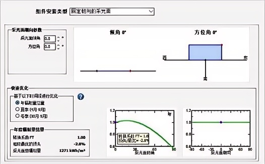
Figure 2-2 Simulation schematic diagram of photovoltaic module installation
2.3 String Design of Photovoltaic System
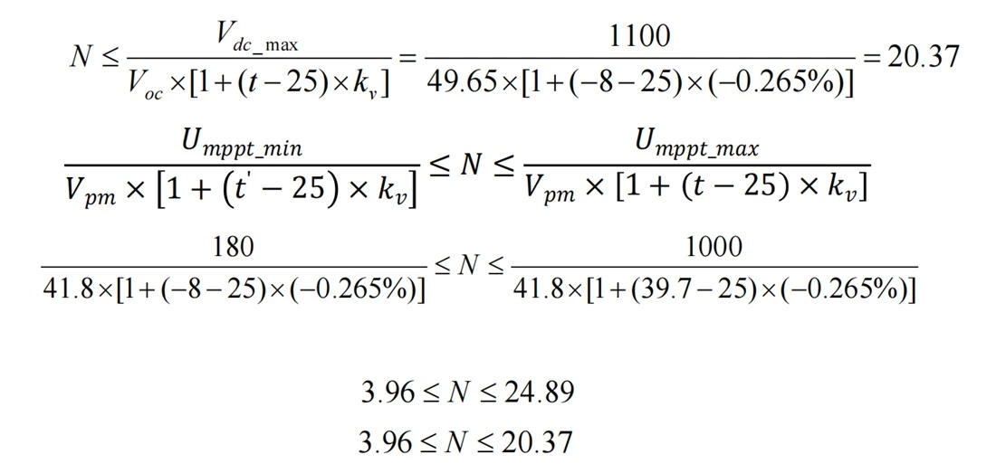
Based on the technical parameters of the selected photovoltaic modules and the historical temperature
conditions (with the highest daytime temperature not exceeding 39.7℃ and
the lowest temperature not lower than -8℃), the number of photovoltaic modules connected in series can
be calculated according to the following formula:
Kv - Open-circuit voltage temperature coefficient of photovoltaic modules
t - The extreme low temperature under the working conditions of photovoltaic modules;
t '- The extreme high temperature under the working conditions of photovoltaic modules;
Vdcmax - The maximum DC input voltage allowed by the inverter;
Vmppt max - Maximum MPPT voltage of the inverter
Vmppt min - Minimum MPPT voltage of the inverter;
VOC - Open-circuit Voltage of photovoltaic modules
Vpm - Working Voltage of photovoltaic modules
N - Number of battery modules connected in series;
Based on the climatic conditions of the project site, the actual situation of the roof, and in combination with the temperature correction coefficient of the battery modules and the optimal input voltage of the inverter, etc., after correction and calculation, the number of solar panel connected in series is taken as: N=18.
Based on the above calculation results, the number of solar panels connected in series is designed to be 18. That is, the solar panels of this project are designed at 18 per series to ensure the stable operation of the system, and the system operation efficiency is relatively high under normal working conditions. As a total of 180 solar panel have been laid in this project, they can be combined into 10 strings in total.
2.4 Photovoltaic and Electrical Access Design
A total of 180 545W solar panel can be installed in the photovoltaic carport of the parking lot, with a total installed capacity of 98.1kW. Therefore, a 100kW string inverter is selected. The number of solar panel connected in series is 18, with each module having a capacity of 545W, meaning each string has a capacity of 9.81kW. As the maximum output power of the inverter is 110kW, the inverter can be connected in parallel with up to 11 strings of solar panel. In this project, the number of parallel strings of solar panel is 10.
It is planned to add one AC grid connection cabinet within the site area. The grid connection cabinet is equipped with a switch to control the inverter current. The schematic diagram of photovoltaic connection is shown in Figure 2-3. In addition, when choosing cables, considering that the temperature in outdoor parking lots is relatively high in summer, cables should be selected based on the condition of 40 ° C. The basis for cable selection is shown in Table 2-3.
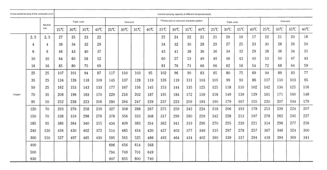
Table 2-3 Basis for Cable Selection
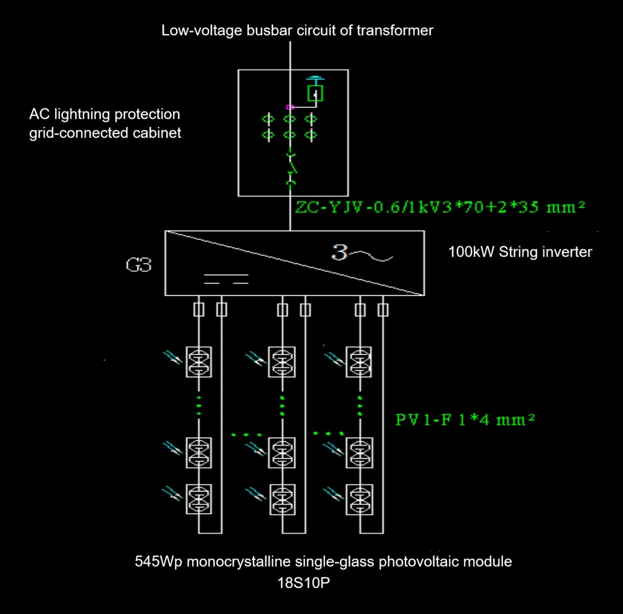
Figure 2-3 Schematic diagram of photovoltaic access
2.5 Security Verification
2.5.1 Thermal stability verification
Low-voltage cables only need to meet the current-carrying capacity and do not require thermal stability verification.
2.5.2 Dynamic Stability verification
No action stability check is carried out.
2.6 Electrical Safety Instructions
2.6.1 Power Quality
Due to the fluctuating and intermittent output of photovoltaic power generation systems, and the fact that
photovoltaic power generation systems convert the DC output from solar cell arrays into
AC through inverters for load use, which contains a large number of power electronic devices, their
connection to the distribution network will have a certain impact on the power quality of the
local power grid. This includes aspects such as harmonics, voltage deviations, voltage fluctuations,
voltage unbalance degrees, and DC components. In order to provide safe and reliable power
to the load, all power quality indicators caused by photovoltaic power generation systems should comply
with the provisions of relevant standards.
(1) After the harmonic photovoltaic power station is connected to the power grid, the harmonic voltage at
the common connection point shall comply with the provisions of
GB/T 14549-1993 "Power Quality - Harmonics in Public Power Grids". After the photovoltaic power station
is connected to the power grid, the total harmonic current component (square mean root)
at the common connection point should meet the provisions of GB/T 14549-1993 "Power Quality - Harmonics in Public Power Grids", and should not exceed the prescribed allowable value.
The allowable value of harmonic current injected into the power grid by photovoltaic power stations should
be allocated in accordance with the ratio of the installed capacity of photovoltaic
power to the total capacity of power generation/supply equipment with harmonic sources at the common
connection points.
(2) Voltage deviation
After the photovoltaic power station is connected to the power grid, the voltage deviation at the common
connection point should comply with the provisions of
GB/ 1225-2008 "Power Quality - Voltage Deviation of Power Supply". The voltage deviation of 10kV
three-phase power supply should be ±7% of the nominal voltage.
(3) Voltage fluctuation
After the photovoltaic power station is connected to the power grid, the voltage fluctuation and flicker at
the common connection point shall comply with the provisions of
GB/T 123262008 "Power Quality - Voltage Fluctuation and Flicker", among which the flicker value caused
by the photovoltaic power station shall be allocated according to the ratio of
the installed capacity of the photovoltaic power station to the total capacity of the disturbance sources at
the common connection point. For the voltage fluctuations caused by the
output changes of photovoltaic power stations, the frequency can be considered as 1<r ≤10(the number
of variations per hour is within 10 times). Therefore, the maximum voltage
variation at the common connection points caused by photovoltaic power stations shall not exceed 3%.
(4) Voltage unbalance degree
After a photovoltaic power station is connected to the power grid, the three-phase voltage unbalance degree at the common connection point should not exceed the limit values
stipulated in GB/T15543-2008 "Power Quality - Three-phase Voltage Unbalance", and the negative sequence
voltage unbalance degree at the common connection point should
not exceed 2%, and for short periods, it should not exceed 4%. Among them, the unbalance degree of
negative sequence voltage caused by photovoltaic power stations should
not exceed 1.3%, and in the short term, it should not exceed 2.6%.
(5) The DC current component injected into the common connection point by a DC component
photovoltaic power station should not exceed 0.5% of its AC rated value.
2.6.2 Response Characteristics in case of abnormal voltage
When a photovoltaic power station is connected to the grid, the output voltage should match the grid
voltage. When the grid connection point voltage is within different
operating ranges, the response requirements of the distributed photovoltaic power generation system to
abnormal grid voltage should comply with the corresponding regulations.
This requirement applies to any phase in a three-phase system. 2.6.3 Response Characteristics when
frequency is abnormal
When photovoltaic power stations are connected to the grid, they should operate in synchronization with
the power grid. When the frequency at the connection point of the
photovoltaic power station exceeds the range of 49.5-50.2 Hz, the photovoltaic power station should stop
supplying power to the power grid lines within 0.2 seconds.
If the system frequency of the photovoltaic power station can be restored to the normal continuous
operation state of the power grid within the specified switching time,
the photovoltaic power station should not stop power supply.
2.6.4 Reactive Power Balance
Photovoltaic power stations should ensure that the power factor at the grid connection point is within the
range of 0.95 (leading) to 0.95 (lagging).
2.6.5 Others
This distributed photovoltaic system should have prominent markings on the dedicated low-voltage
switch cabinet connected to the power supply and the power grid.