This system is a wall photovoltaic system installation structure suitable for the exterior facades of new buildings or existing buildings. It adopts a column + beam aluminum alloy bracket structure to stably install photovoltaic modules on the exterior wall surface. The support system is fixed to the reinforced concrete wall through chemical anchor bolts or expansion bolts and passes through the rock wool insulation layer. All crossing points are treated with fireproof sealing to ensure the overall fire safety performance of the system.
Photovoltaic modules are connected to the crossbeams through rails, fixtures or slides, and rubber joints are reserved between the modules to take into account both drainage and thermal expansion and contraction. The system is equipped with complete equipotential bonding and grounding protection measures. Grounding wires are set between components, beams and columns, and are reliably connected to the building grounding system through grounding busbars, meeting the requirements of lightning protection and electrical safety regulations.
In the roof and facade system, for the pre-embedded parts of the photovoltaic support on the TPO waterproof membrane roof, a TPO prefabricated flooding structure is adopted, with an upward tilt height of ≥250mm. The joints between the membranes are welded by hot air, and reinforced with metal hoops and general sealant to ensure the long-lasting waterproof performance of the system.
This structural system takes into account the safety of building structures, waterproofing, fire protection, electrical protection and construction convenience. It is suitable for the installation scenarios of facade and roof photovoltaic systems in industrial and commercial BIPV/BAPV projects.
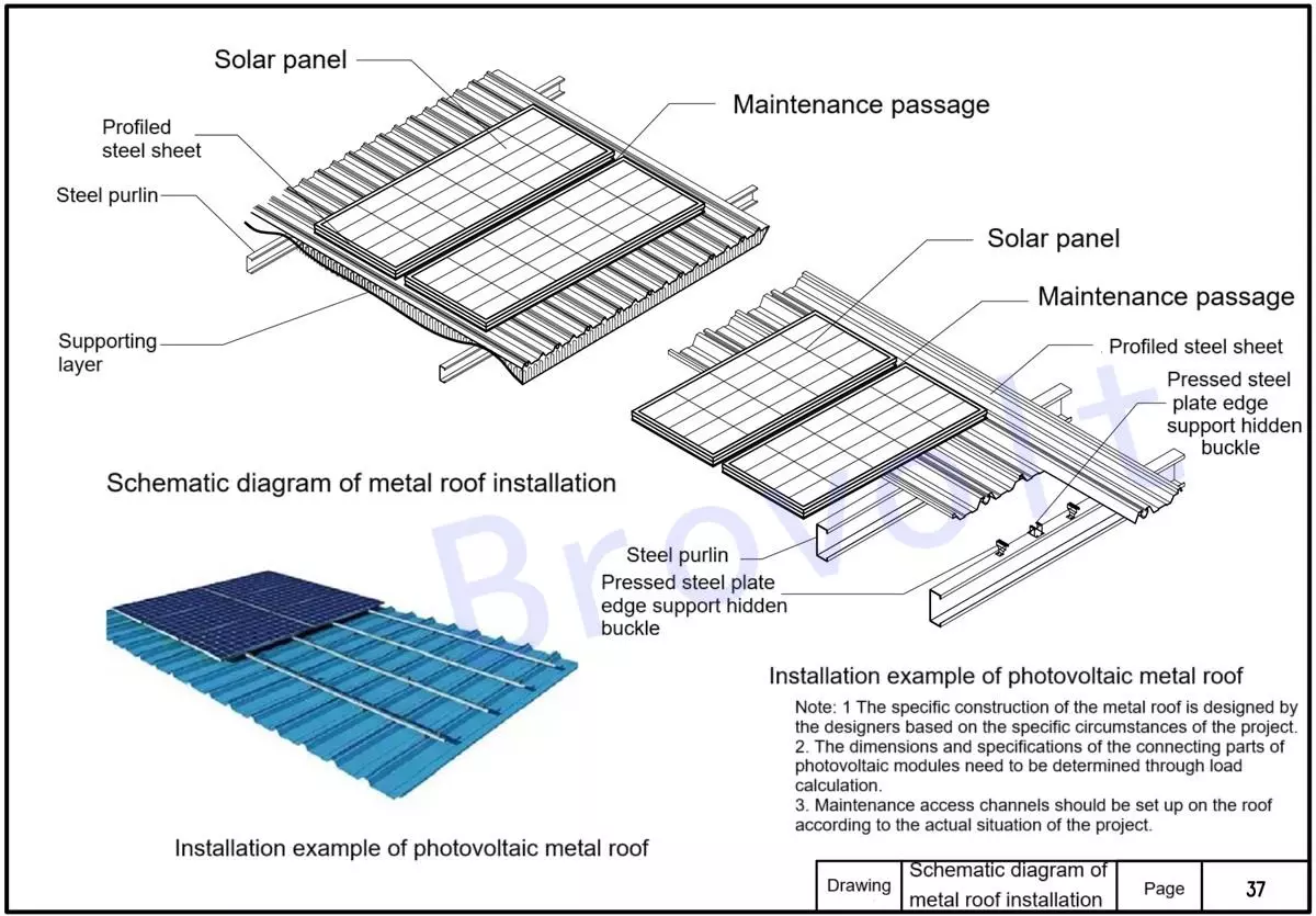
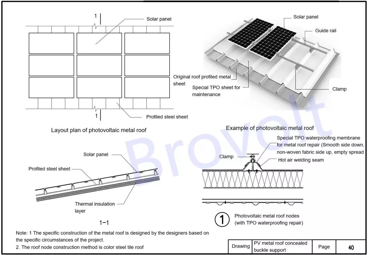
Schematic diagram description of the installation structure of photovoltaic metal roof
1.Solar panels
Solar panels are installed on the metal roof and fixed through a bracket system.The component arrangement should reserve maintenance channels.
2. Maintain the passage
Set between PV arrays, it is convenient for daily cleaning, maintenance and fire escape.The width is usually no less than 600mm, and the position is reserved according to the design requirements.
3. Solar bracket system
Medium bracket concealed couplings/bracket concealed couplings: used for connecting and fixing PV brackets to the roof system;The fixation method should be determined based on the roof slope and wind load.The concealed buckle design reduces damage to the roof structure and ensures the waterproofing effect.
4. Profiled steel sheet/profiled metal sheet
It is the main load-bearing surface layer of metal roofs, with common models such as YX35-125-750.It is connected to the lower structure through self-tapping nails or interlocking methods.
It has good drainage performance and wind resistance.
5. Steel purlins
It serves to support the profiled steel sheet and generally uses C-shaped or Z-shaped steel.The installation spacing should be determined based on the design load calculation.
6. Supporting Layer
If necessary, set up insulation cotton, vapor barrier layer, waterproof membrane, etc.The specific approach is determined by the designers based on the actual project.
7. Waterproof treatment
Roof drilling should be avoided as much as possible. If it is necessary to drill holes, they should be strictly sealed with sealing gaskets and waterproof glue.The use of concealed lock systems or standing seam metal plates can effectively reduce the risk of water leakage.
Installation precautions
Design basis for installation methods
All connecting parts (including fixtures and guide rails) must be selected in terms of model and quantity based on the structural calculation results such as wind load and snow load.
It is recommended to use aluminum alloy or stainless steel materials to prevent corrosion.
Schematic diagram of PV metal roof installation
PV metal roof concealed buckle support 1
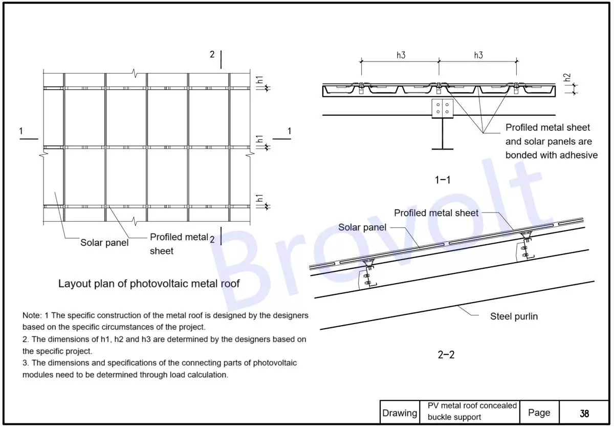
Structural description of the photovoltaic metal roof layout plan
1.Photovoltaic module
Solar panels are fixed to the bracket through connecting pieces.The installation direction and slope should be optimally designed based on the sunlight conditions of the project site.
2.Concealed buckle bracket
A fixed support system specially designed for metal roofs;It does not penetrate the roof panel to ensure waterproof performance.It is connected to the profiled steel sheet through concealed interlocking.
3.Profiled steel sheet
The main covering material for metal roofs;Usually, galvanized or aluminized zinc steel plates are used, with a thickness of 0.5mm to 0.8mm.It needs to be reasonably connected with the supporting structure to ensure load transfer.
4.Thermal insulation layer
Common materials include rock wool, glass wool, polyurethane boards, etc.Improve the insulation performance of the roof and reduce the energy consumption for cooling and heating.
5.Supporting layer
The base layer supporting insulation materials and profiled steel sheets;It could also be a concrete slab, a steel structure platform or other base.
6.Steel purlins (steel marking strips)
The secondary structure that supports the entire roofing system;Mostly C-shaped or Z-shaped hot-dip galvanized steel, the spacing is set according to the structure calculation.It is welded or bolted to the main structural beams and columns.
PV metal roof concealed buckle support 2
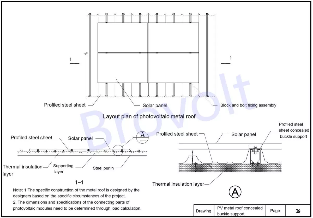
Structural composition description of photovoltaic metal Roofing system
Layout structure
1.Photovoltaic module
Installed on the guide rail and connected to the fixture;The spacing and arrangement of components should be designed in combination with maintenance channels, safety distances, etc.
2.Guide rail
It is usually an aluminum alloy track;Lay horizontally and connect with the fixture;Waterproof treatment should be set up between the guide rail and the roof.
3.Fixture (fixed part)
It is used to fix the guide rail to the original roof profiled sheet or support.The types are divided into non-penetrating fixtures and penetrating fixtures.It is recommended to adopt a non-penetrating design and pair it with TPO rolls to enhance water resistance.
4.Original roof profiled metal sheet
The original roof panels of the building are used as the installation base surface.Maintain the original slope and drainage design.TPO waterproofing membrane for metal roofs
5.Construction description
The smooth side faces down and the non-woven fabric side faces up.The roll material is laid empty and not fully adhered.The lap joints are sealed by hot air welding to prevent rainwater from seeping in.Additional gaskets or sealants should be added between the roll material and the fixture to ensure that the waterproof layer is not damaged.
6.Thermal insulation layer Such as rock wool boards, polyurethane boards, etc.It should be compacted and laid to prevent thermal Bridges or collapse.
7.Supporting layer/profiled steel sheet
Support the roof and insulation layer;It is usually steel purlins or a concrete base.
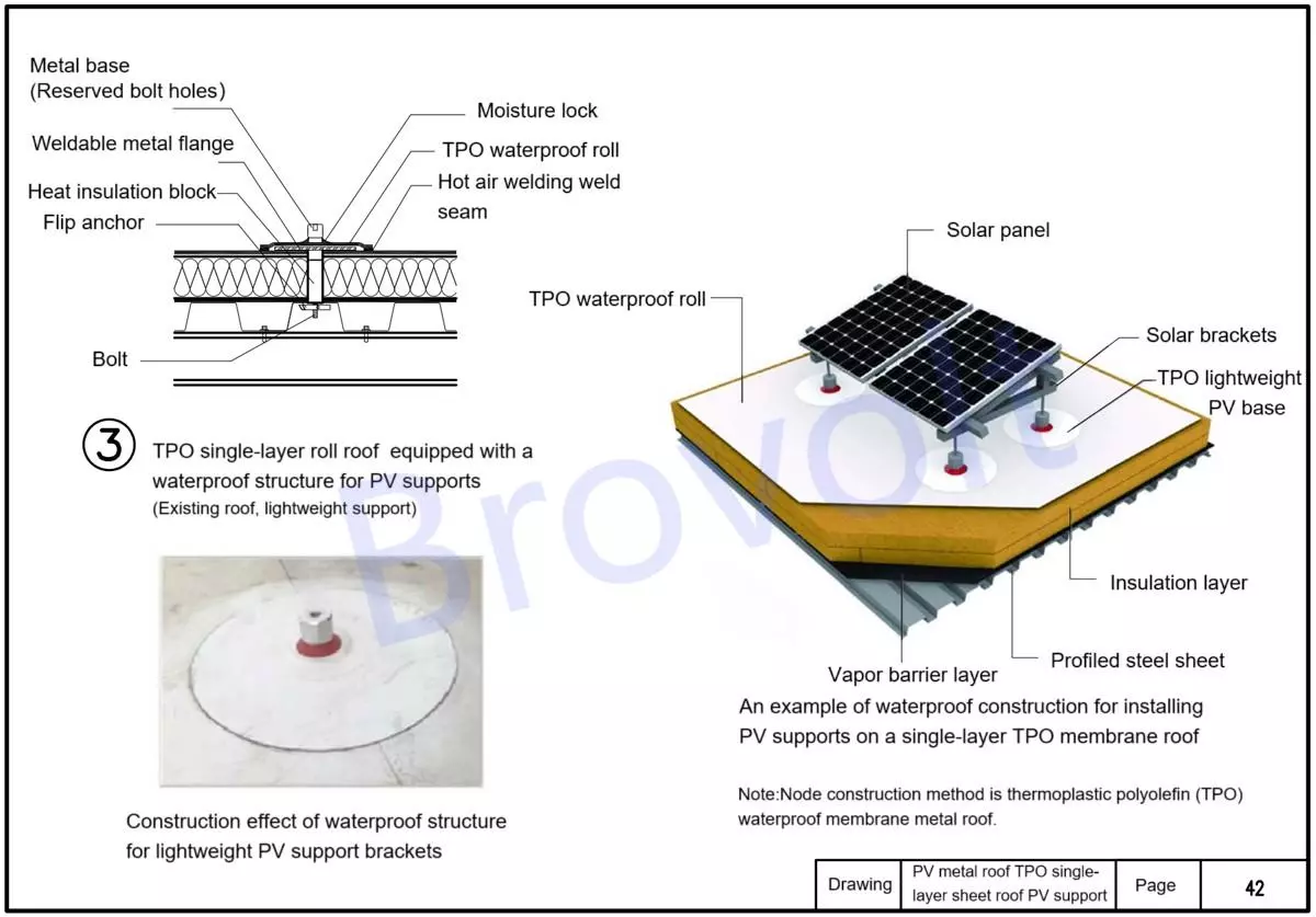
PV metal roof concealed buckle support 3
Photovoltaic module base
1. Support photovoltaic brackets and modules;
It is connected to the pillar and has a sealing treatment at the bottom to prevent rainwater from seeping into the structural layer.
2. Universal sealant
Used for sealing the gap between the base and the TPO roll material;It should be an environmentally friendly high-elastic sealant compatible with TPO.
3.TPO waterproofing membrane
Main materials for single-layer roof waterproofing;The smooth side faces down and the non-woven fabric side faces up.
Laying method: Full bonding or empty laying. The lap joints are welded with hot air.The upward flipping height of the floodwater prefabricated component is ≥250mm (used for the coil wrapping at the part where the steel column passes through the roof).
4. Coil fasteners
The edges and detailed structures of the mechanically fixed waterproof layer (such as around the pillars);After installation, the waterproof layer needs to be sealed at the edge seams by hot air welding.
5.TPO pipe root prefabricated parts/flooding
Waterproof treatment specifically for exit points (such as steel columns);Finished products are prefabricated, tightly wrapped, with an upward flip of ≥250mm, and fixed to the roll layer by hot air welding.It must be combined with metal hoops and sealant for secondary sealing to ensure no leakage.
6. Photovoltaic module brackets/photovoltaic system brackets
Weld or bolt to the reserved steel column;It should meet the requirements of structural load calculation and wind resistance design.
7. Metal hoop
Installed at the flanged part of the TPO flashing water;When used in conjunction with sealant, it forms a tight seal on the waterproof prefabricated components.
8. Insulation layer
Insulation boards such as rock wool, extruded polystyrene boards or polyurethane;Lay it flat without damage to ensure the thermal performance of the structure.
9. Vapor barrier
Block water vapor from entering the insulation layer;It is recommended to use high-performance vapor barrier membranes that are compatible with the roll material system.
10. Profiled steel sheet (roof bearing)
Bear the load of the roof structure;It is fixed by welding or bolted to the steel beam.
11. Roof steel beams
For the main structure section, weld the reserved steel columns for photovoltaic.An important support point for installing photovoltaic bracket systems.
12. Steel column/reserved pillar type photovoltaic support
Pre-embed or penetrate the profiled steel sheet and anchor it to the steel beam;
It must be tightly sealed with water in coordination with the coil system, and the structural details must be treated by hot air welding.
PV metal roof TPO single-layer sheet roof PV support 1
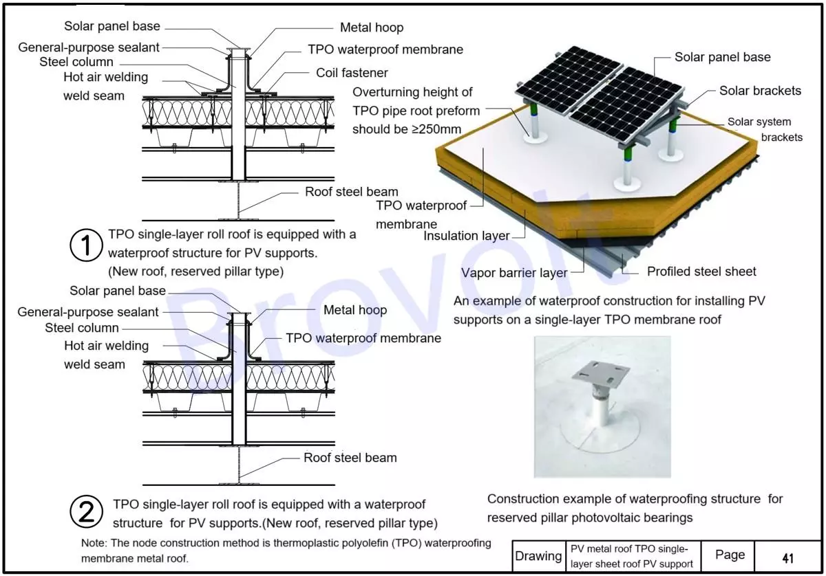
PV metal roof TPO single-layer sheet roof PV support 2
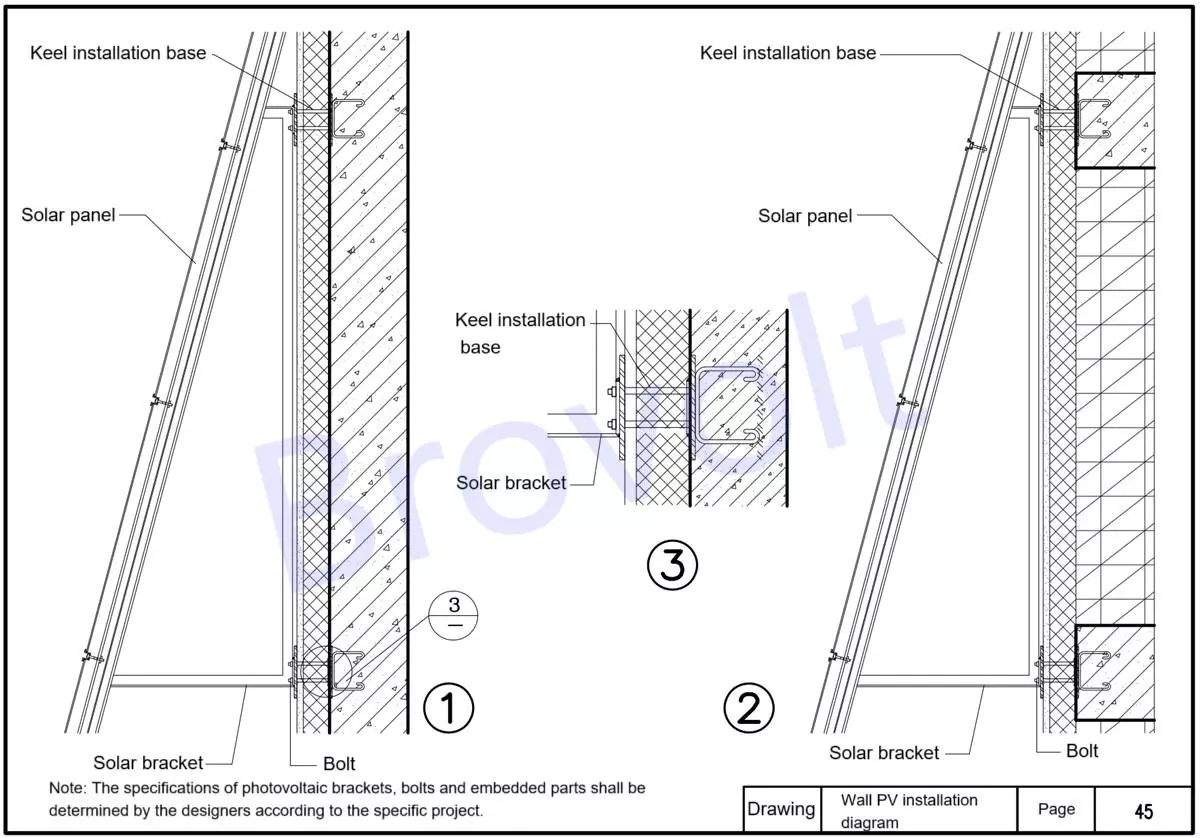
Wall PV installation diagram & grounding structure description
I. Structural Composition
The main wall: A reinforced concrete structure serves as the primary load-bearing structure of the building, providing the installation foundation for the solar bracket system.
Rock wool insulation layer: Fireproof A-level material; Installed on the outer surface of concrete walls, it is used for energy conservation and insulation in buildings. Fireproof seals are set between the brackets to prevent the spread of fire.
Column (vertical profile) : Fixed to the building wall by means of expansion bolts, chemical anchor bolts, etc. Bear the weight of the solar system and transfer the load to the wall; The connection with the crossbeam adopts a screw connection or chute structure.
Crossbeam (transverse keel) : Undertakes the direct installation of solar panels; Set anti-slip grooves or pressure blocks to fix the components; The spacing of the crossbeams is determined based on the size of the photovoltaic modules and the wind resistance design.
Solar panel: Installed on the beam system; There are glue gaps (usually 5 to 10mm) left between the modules to buffer thermal expansion and contraction and to drain water.The back should maintain a ventilation gap to prevent heat accumulation.
Joint: Weather-resistant sealant is filled between components or structural adhesive is used for bonding. It has the functions of drainage and buffering.
Ii. Equipotential Bonding and Grounding Systems (Electrical Safety)
Grounding connection instructions for solar panels: Each solar panel is electrically connected to the crossbeam or support system through copper braided tape or grounding wire. The support system is connected to the equipotential busbar through the main grounding wire (PE). The entire system should form a continuous equipotential connection closed loop to ensure balanced potential in case of leakage or lightning strike.
Grounding construction requirements: The cross-sectional area of the grounding wire shall not be less than 4mm² (copper wire). The joints are made by crimping and bolt connection, and undergo anti-corrosion treatment.
Iii. Fireproof Sealing Instructions
When PV support structures pass through the insulation layer, all crossing points must be sealed with fireproof materials (such as fireproof mud, expansion sealing strips).
Fireproof sealing should be continuous and uninterrupted, especially at the contact points between the columns and the walls.
Prevent the spread of fire through structural gaps in case of fire.
Iv. Construction Precautions
All bolt connections must be coated with anti-corrosion materials.
A ventilation cavity of ≥50mm should be reserved between the back of solar panel and the wall.
Wall PV installation diagram 1
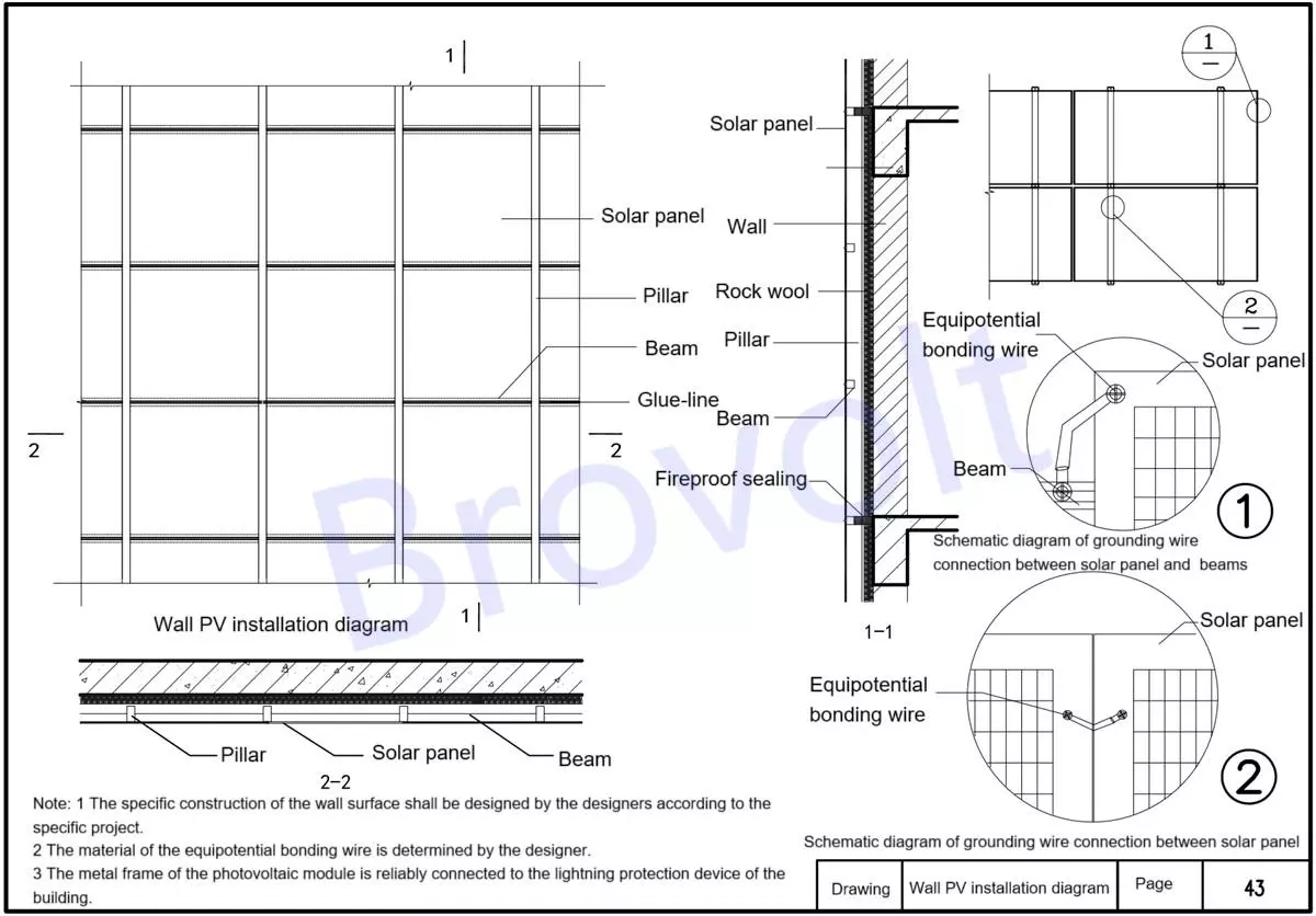
Wall PV installation diagram 2
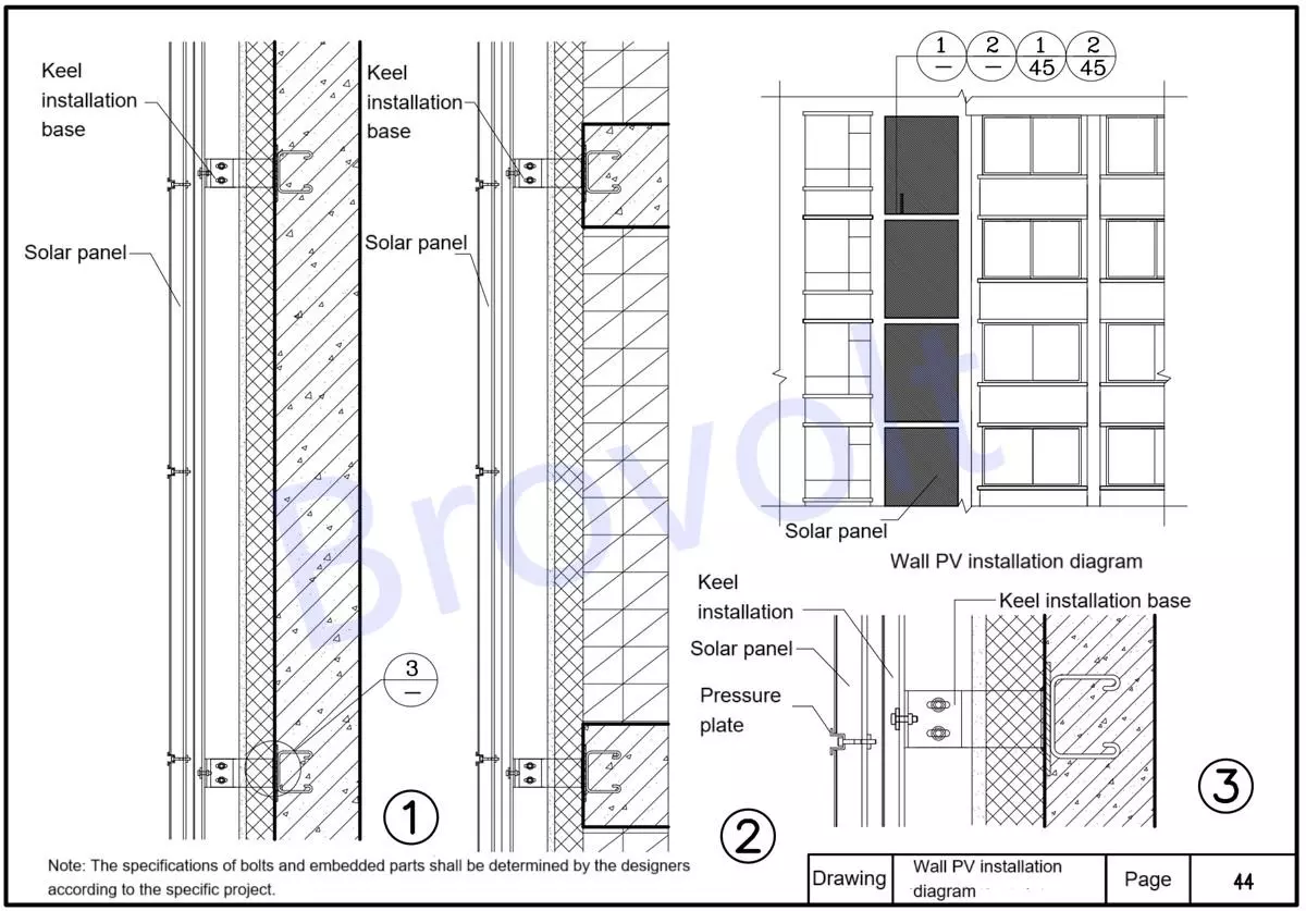
Wall PV installation diagram