This project involves the construction of a distributed photovoltaic power generation system on the rooftop of a single-story industrial plant. The plant features a bent-frame structure with a steel truss roof, covering a total area of approximately 2,781.14 square meters. The design incorporates 384 monocrystalline silicon 535Wp photovoltaic modules on the rooftop, with a total installed capacity of 205.44kWp. These modules are equipped with two 100kW grid-connected inverters, connected to the plant's low-voltage power distribution system via a grid-connected cabinet. The system utilizes a fixed installation, fully utilizing the rooftop's resources and enabling unobstructed power generation throughout the day from 9:00 AM to 3:00 PM on the winter solstice. The design comprehensively considers structural loads, safety protection, grounding, and lightning protection requirements to ensure safe, stable, and efficient operation of the system over its 25-year design lifespan, providing strong support for the company's energy conservation, emission reduction, and green production efforts.
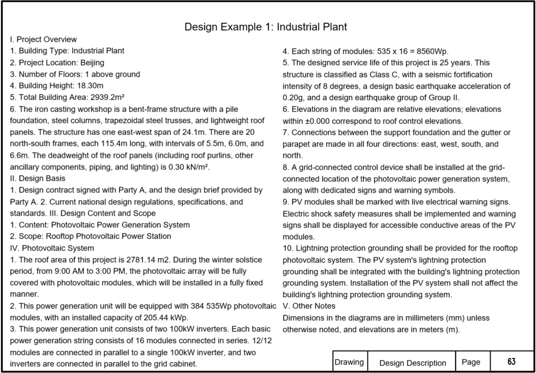
I. Project Overview
1. Building Type: Industrial Plant
2. Project Location: Beijing
3. Number of Floors: 1 above ground
4. Building Height: 18.30m
5. Total Construction Area: 2939.2㎡
6.The shaped cast iron workshop is a bent-frame structure with a pile foundation, steel trusses, trapezoidal steel trusses, and a lightweight roof panel. The structure has one east-west span of 24.1m. There are 20 bent-frames running north-south, with a length of 115.4m. The bays are spaced 5.5m, 6.0m, and 6.6m apart. The roof panel deadweight (including roof purlins, other ancillary components, piping, and lighting) is 0.30 kN/㎡
II. Design Basis
1. Design contract signed with Party A, and design brief provided by Party A;
2. Current national design regulations, specifications, and standards.
III. Design Content and Scope
1. Content: Photovoltaic power generation system
2. Scope: Rooftop photovoltaic power station.
IV. Photovoltaic System
1. The roof area of this project is 2781.14 ㎡. During the winter solstice period, from 9:00 a.m. to 3:00 p.m., the photovoltaic array will be fully covered with solar panels, which will be installed in a fully fixed manner.
2. This power generation unit will be equipped with 384 pieces of 535Wp photovoltaic modules, with an installed capacity of 205.44 kWp.
3. This power generation unit consists of two 100kW inverters. Each basic power generation string consists of 16 modules connected in series. 12/12 modules are connected in parallel to a single 100kW inverter, and two inverters are connected in parallel to the grid cabinet.
4. Each string of modules: 535 x 16 = 8560Wp.
5. The design life of this project is 25 years. The structural importance of this structure is Class C, the seismic fortification intensity is 8, the design basic earthquake acceleration is 0.20g, and the design earthquake group is Group II.
6. Elevations in the figure are relative elevations; the elevation corresponding to 0.000 is the roof control elevation.
7. Connections between the support foundation and the gutter or parapet are made in all four directions: east, west, south, and north.
8. A grid-connected control device shall be installed at the grid-connected location of the solar power generation system, along with dedicated signs and warning symbols.
9. PV modules shall be marked with live electrical warning signs. Electric shock safety measures shall be implemented and warning signs shall be posted for accessible conductive areas of the PV modules.
10. Lightning protection grounding shall be provided for the rooftop photovoltaic system. The PV system lightning protection grounding shall be integrated with the building's lightning protection grounding system. The installation of the PV system shall not affect the building's lightning protection grounding system.
V. Other Notes
Dimensions in the figures are in millimeters (mm) unless otherwise noted, and elevations are in meters (m).
Industrial PV System Design Description
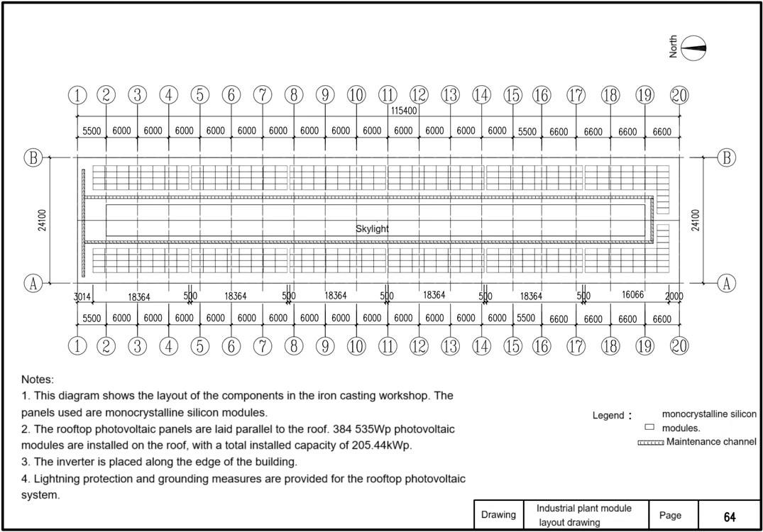
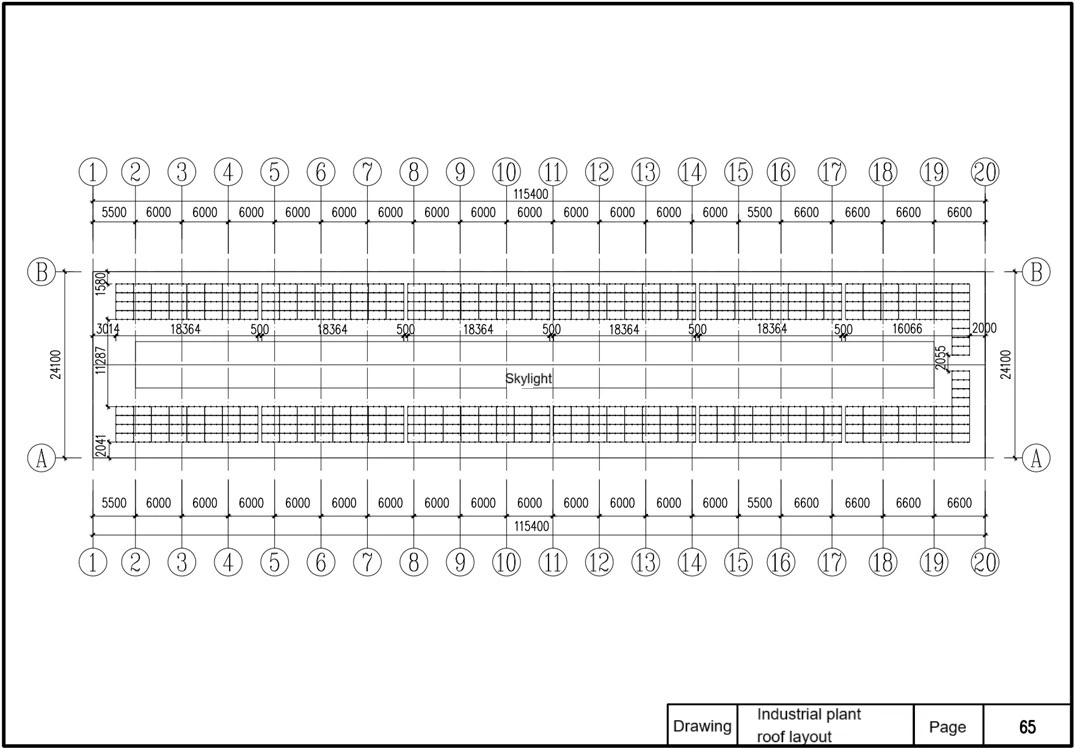
Industrial Plant Module Layout Drawing
Notes:
1. This diagram shows the layout of the components in the iron casting workshop. The panels used are monocrystalline silicon solar cells.
2. The rooftop photovoltaic panels are laid parallel to the roof. 384 535Wp photovoltaic modules are installed on the roof, with a total installed capacity of 205.44kWp.
3. The inverter is placed along the edge of the building.
4. The rooftop photovoltaic system is equipped with lightning protection and grounding measures.
Industrial Plant Module Layout Drawing
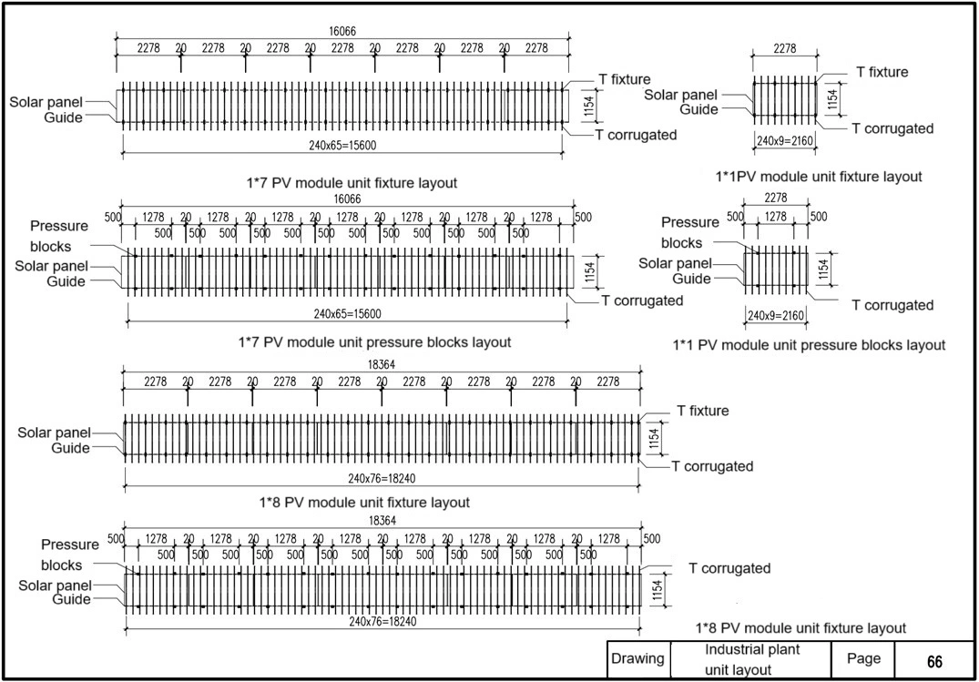
Industrial Plant Unit Layout
T-shaped clamps are used in conjunction with guide rails to secure PV modules to the roof structure. T-shaped corrugations are designed to adapt to the shape of the roof panels, ensuring stability and waterproofing.
The 1×7 Module Unit Clamp Layout and 1×1 Module Unit Clamp Layout diagrams correspond to the clamp installation positions for seven modules and a single module, respectively.
The 1×7 Module Unit Clamp Layout and 1×1 Module Unit Clamp Layout diagrams show the installation layout of the clamps.
The 1×8 Module Unit Clamp Layout and 1×8 Module Unit Clamp Layout diagrams are for mounting eight modules.
The Industrial Plant Unit Layout diagram shows the overall layout of PV panels on the entire plant roof, providing a reference for installation.
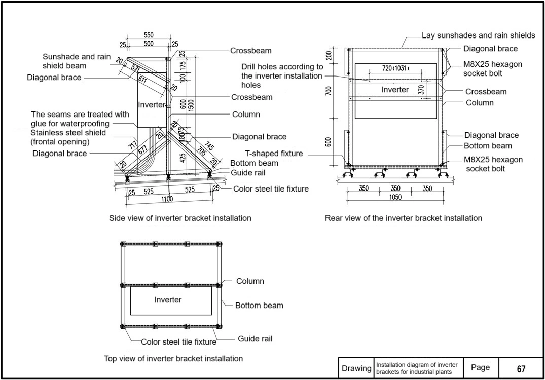
Inverter Bracket Installation Diagram
Sunshade and rain shield beams: Installed above the inverter, they provide rain and sun protection, extending the life of the equipment.
M8×25 hexagonal bolts: Used to secure key connection points, ensuring a secure connection between the bracket and components.
Diagonal braces (No. 3): Connect the columns and crossbeams, enhancing structural stability and wind resistance.
Crossbeam and bottom beam: Serving as the primary load-bearing structure of the inverter bracket, the crossbeam bears the weight of the inverter, while the bottom beam provides overall support.
Columns: Secure the bottom beam, crossbeam, and diagonal braces to the ground or foundation.
Seams are waterproofed with glue to prevent rainwater infiltration and protect electrical equipment.
Stainless steel shield (front-openable): Provides physical protection for the inverter and facilitates maintenance and inspection. T-shaped clamps and guide rails: Used to secure PV panels. Combined with the color-coated steel tile clamps, they ensure a safe and stable rooftop installation.
Color-coated steel tile clamps: Adapt to metal roofs and securely connect the bracket to the roof.
Drawings include:
Inverter bracket installation side view: Shows the structural relationship between the columns, beams, braces, and shield from the side.
Inverter bracket installation rear view: Shows the overall layout of the inverter, shield, and bracket from the rear.
Inverter bracket installation top view: Provides a top-down view of the installation position and component relationships, facilitating overall layout and measurement.
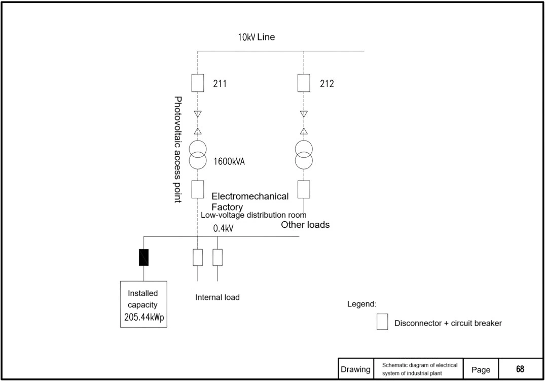
Electrical System Diagram
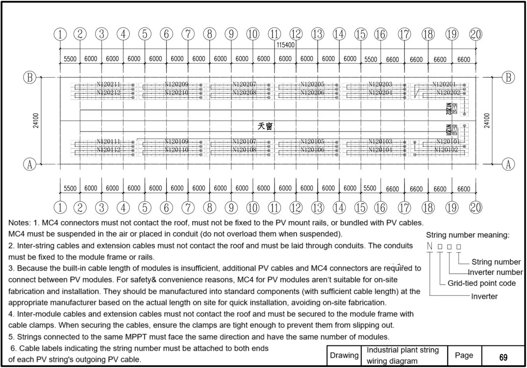
PV String Wiring Diagram
Notes:
1. MC4 connectors must not contact the roof, must not be fixed to the PV mount rails, or bundled with the PV cables. MC4 connectors must be suspended in the air or placed in conduit (do not overload them when suspended).
2. Inter-string cables and extension cables must not contact the roof and must be laid through conduits. The conduits must be fixed to the module frame or rails. 3. Because the built-in cable length of the modules is insufficient, additional PV cables and MC4 connectors are required to connect between PV modules. For safety and convenience reasons, MC4 connectors for PV modules are not suitable for on-site fabrication and installation. They should be manufactured into standard components (with sufficient cable length) at the appropriate manufacturer based on the actual length on site for quick installation, avoiding on-site fabrication. 4. Inter-module cables and extension cables must not contact the roof and must be secured to the module frame with cable clamps. When securing the cables, ensure the clamps are tight enough to prevent them from slipping out.
5. Strings connected to the same MPPT must face the same direction and have the same number of modules. 6. Cable labels indicating the string number must be attached to both ends of each PV string's outgoing PV cable.
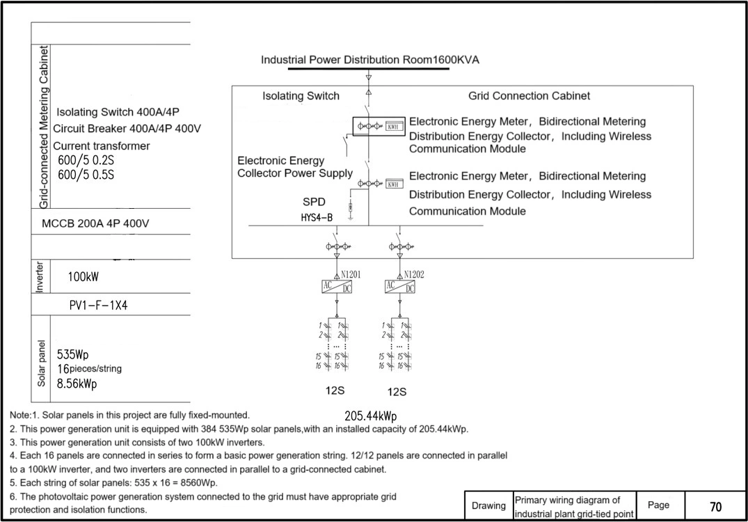
Primary Wiring Diagram of Grid Connection Point
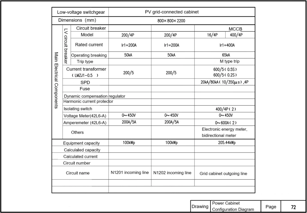
1. PV Array Configuration
Solar panels: 535 Wp Monocrystalline Silicon Modules
Number of PV modules: 384
Single String Configuration: 16 modules connected in series form a basic generating string, with a single string power of 8.56 kWp (535 Wp x 16 modules);
Parallel Connection and Inverter Connection: 1 100 kW inverter is connected for every 12 strings connected in parallel, with two inverters connected in parallel to a grid-connected cabinet;
Total Installed Capacity: 205.44 kWp (8.56 kWp x 24 strings).
2. Inverter Configuration
Number of Inverters: 2
Single Unit Capacity: 100 kW
Connection Method: Parallel connection to a grid-connected cabinet.
3. Grid Connection and Power Distribution Equipment
Grid Connection Cabinet:
Disconnector 400A/4P (isolation device for photovoltaic power connection);
Circuit Breaker 400A/4P 400V;
HYS4-B Surge Protector;
Electronic bidirectional energy meter (with wireless communication module and energy collector);
600/5 current transformer (one set each with accuracy class 0.2s and 0.5s).
Grid-connected metering cabinet: Provided by the power supply bureau, meeting photovoltaic grid-connected metering requirements.
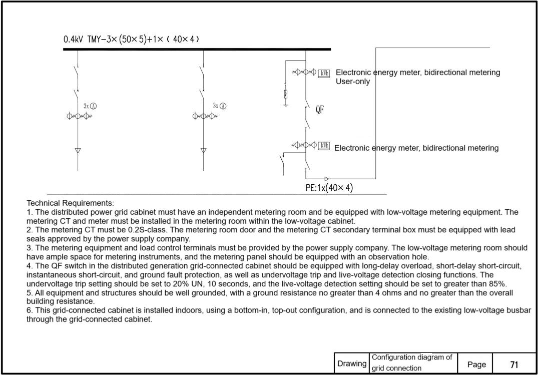
Grid Cabinet Configuration Diagram
Technical Requirements:
1. The distributed generation grid-connected cabinet must have an independent metering room and be equipped with low-voltage metering equipment. The metering CT and meter must be installed in the metering compartment within the low-voltage cabinet.
2. The metering CT must be 0.2S-class. The metering room door and the secondary terminal box of the metering CT must be equipped with lead seals approved by the power supply company.
3. The metering equipment and load control terminals must be provided by the power supply company. The low-voltage metering room should have ample space for metering instruments, and the metering panel should be equipped with an observation hole.
4. The QF switch in the distributed generation grid-connected cabinet should be equipped with long-delay overload, short-delay short-circuit, instantaneous short-circuit, and ground fault protection, as well as undervoltage trip and live-voltage detection closing functions. The undervoltage trip setting should be set to 20% UN, 10 seconds, and the live-voltage detection setting should be set to greater than 85%.
5. All equipment and structures should be well grounded, with a ground resistance no greater than 4Ω and no greater than the overall building resistance.
6. This grid-connected cabinet is installed indoors, using a bottom-in, top-out configuration, and is connected to the existing low-voltage busbar through the grid-connected cabinet.
Grid Cabinet Configuration Diagram
Notes:
1. This project's main grounding grid utilizes 40x4 hot-dip galvanized flat steel.
2. All live metal conductors on the roof, including solar panels, inverters, and cable trays, must be reliably grounded. The grounding resistance should not exceed 40Ω and should not exceed the overall building resistance.
3. This project's roof already has a comprehensive lightning protection system, with lightning rods laid crisscrossing the roof. New lightning rods for the photovoltaic system will be grounded by reliably welding them to the existing lightning rods.
4. The flat steel shown in this diagram should be placed 10cm along the module edge. The position may be adjusted based on actual site conditions. Any adjustments require approval from the design institute before construction can begin.
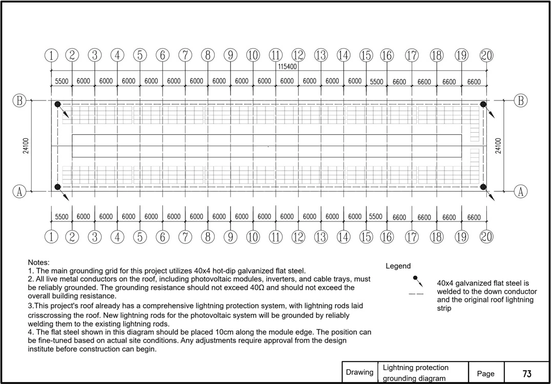
Lightning Protection Grounding Diagram
Notes:
1. This project's main grounding grid utilizes 40x4 hot-dip galvanized flat steel.
2. All live metal conductors on the roof, including solar panels, inverters, and cable trays, must be reliably grounded. The grounding resistance should not exceed 40Ω and should not exceed the overall building resistance.
3. This project's roof already has a comprehensive lightning protection system, with lightning rods laid crisscrossing the roof. New lightning rods for the photovoltaic system will be grounded by reliably welding them to the existing lightning rods.
4. The flat steel shown in this diagram should be placed 10cm along the module edge. The position may be adjusted based on actual site conditions. Any adjustments require approval from the design institute before construction can begin.